Cat. No. I129E-EN-01
MX2
Born to drive machines
Model: MX2
200 V Class Three-Phase Input 0.1 to 15 kW
200 V Class Single-Phase Input 0.1 to 2.2 kW
400 V Class Three-Phase Input 0.4 to 15 kW
QUICK START GUIDE
MX2 Quick Start Guide
1 SPECIFICATIONS
3
1.1 Upon receipt
3
1.2 Technical specification
4
1.3 Power ratings
4
2 INSTALLATION
6
2.1 Wiring sizes and protection
6
2.2 External dimensions for installation (IP20 & IP54)
6
2.3 Installation Environment clearance
9
2.4 Wiring overview
10
2.5 Power wiring
11
2.6 Control wiring
11
2.7 Screwless terminals connection
12
2.8 Digital inputs SINK/SOURCE (NPN/PNP) settings
13
2.9 Safe stop disable function
13
3 PROGRAMMING MX2
.....................................................................14
3.1 Digital operator
14
3.2 Keypad navigation
15
3.3 Initialization
15
3.4 Inverter modes
16
3.5 Basic settings
17
3.6 Auto tuning (SLV Mode)
18
3.7 Ramps adjustment
20
3.8 DC Braking
21
3.9 V/F Curve
22
3.10 Torque boost function
23
3.11 Analog inputs
24
3.12 Digital inputs
25
3.13 Digital outputs
27
3.14 Pulse input
29
3.15 Analogue and pulse outputs
30
3.16 Torque limit
30
3.17 Torque control
31
3.18 Electronic thermal overload
31
3.19 Carrier frequency (PWM)
32
3.20 PID Function
33
3.21 Current limitation functions
33
3.22 Overvoltage protection
34
3.23 Controlled stop at power loss
35
4 PARAMETER LIST
35
4.1 Parameter group D: Monitors
35
4.2 Parameter group A
36
4.3 Parameter group B
39
4.4 Parameter group C
41
4.5 Parameter group H
42
4.6 Parameter group P
43
4.7 Parameter group F
45
4.8 Parameter group U: User parameters
45
MX2 Quick Start Guide Draft
1
2
MX2 Quick Start Guide Draft
MX2 Quick Start Guide
1 SPECIFICATIONS
1.1 Upon receipt
Please perform the following task after receiving the drive:
• Inspect the driver for damage. If the drive appears to be damaged upon receipt, contact your supplier
• Verify the receipt of the correct model by checking the information on the nameplate. If you have received the wrong model
contact your supplier.
• Refer to the User’s Manual for detailed information about the product and functions
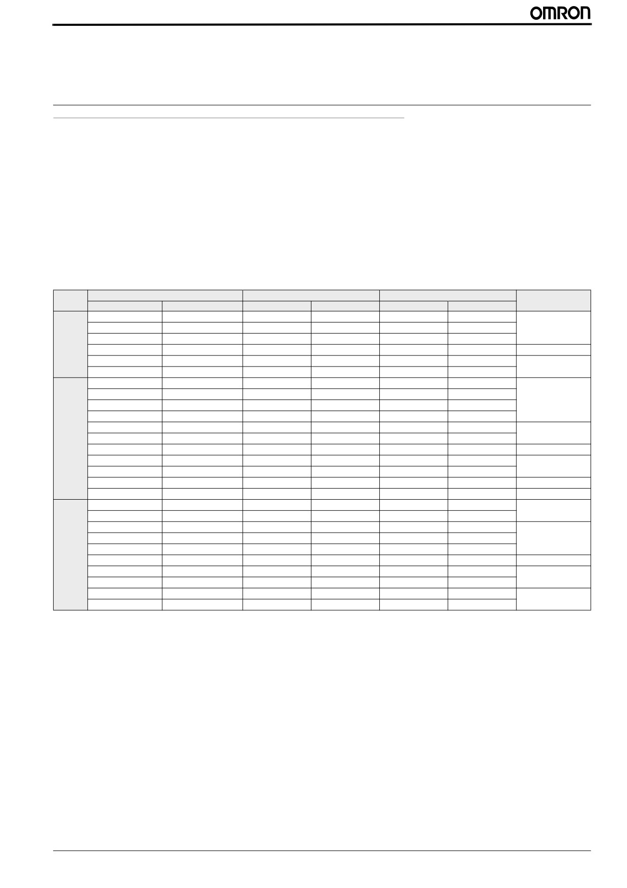
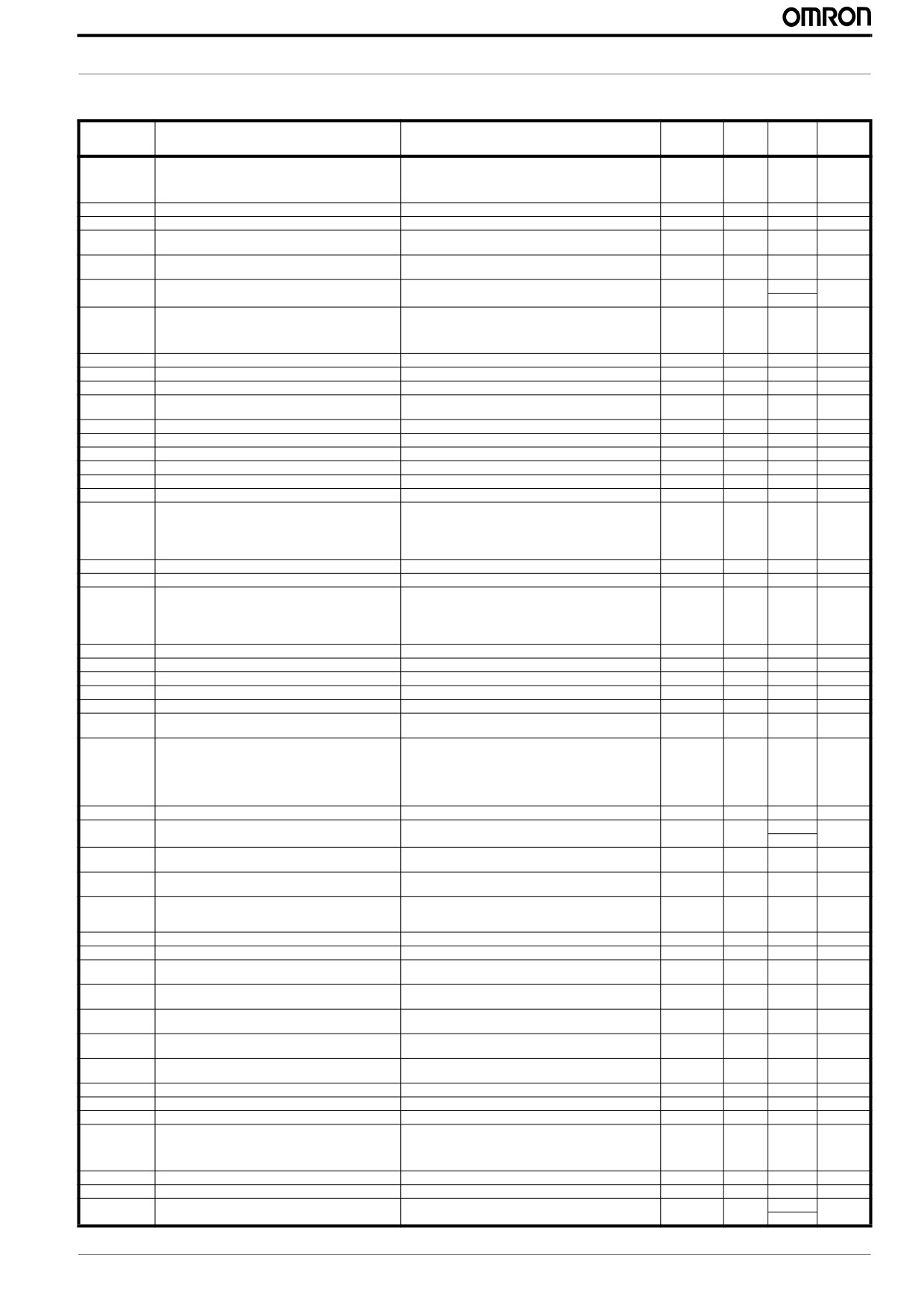
Basic specifications and EMC filter
Type
HD (150% overload for 60s)
ND (120% overload for 60s)
Voltage
EMC filter*
IP20
IP54
Max Motor (KW)
Rated current (A)
Max Motor (KW)
Rated current (A)
3G3MX2-AB001-E
3G3MX2-DB001-E/EC
0.1
1.0
0.2
1.2
AX-FIM1010-RE
3G3MX2-AB002-E
3G3MX2-DB002-E/EC
0.2
1.6
0.4
1.9
AX-FIM1014-SE
3G3MX2-AB004-E
3G3MX2-DB004-E/EC
0.4
3.0
0.55
3.5
1 x 230 V
3G3MX2-AB007-E
3G3MX2-DB007-EC
0.75
5.0
1.1
6.0
AX-FIM1014-RE/SE
3G3MX2-AB015-E
3G3MX2-DB015-EC
1.5
8.0
2.2
9.6
AX-FIM1024-RE/SE
3G3MX2-AB022-E
3G3MX2-DB022-EC
2.2
11.0
3.0
12.0
3G3MX2-A2001-E
3G3MX2-D2001-E/EC
0.1
1.0
0.2
1.2
3G3MX2-A2002-E
3G3MX2-D2002-E/EC
0.2
1.6
0.4
1.9
AX-FIM2010-RE/SE
3G3MX2-A2004-E
3G3MX2-D2004-E/EC
0.4
3.0
0.55
3.5
3G3MX2-A2007-E
3G3MX2-D2007-E/EC
0.75
5.0
1.1
6.0
3G3MX2-A2015-E
3G3MX2-D2015-EC
1.5
8.0
2.2
9.6
AX-FIM2020-RE/SE
3 x 230 V
3G3MX2-A2022-E
3G3MX2-D2022-EC
2.2
11.0
3.0
12.0
3G3MX2-A2037-E
3G3MX2-D2037-EC
3.7
17.5
5.5
19.6
AX-FIM2030-RE/SE
3G3MX2-A2055-E
3G3MX2-D2055-EC
5.5
25.0
7.5
30.0
AX-FIM2060-RE/SE
3G3MX2-A2075-E
3G3MX2-D2075-EC
7.5
33.0
11
40.0
3G3MX2-A2110-E
3G3MX2-D2110-EC
11
47.0
15
56.0
AX-FIM2080-RE/SE
3G3MX2-A2150-E
3G3MX2-D2150-EC
15
60.0
18.5
69.0
AX-FIM2100-RE/SE
3G3MX2-A4004-E
3G3MX2-D4004-EC
0.4
1.8
0.75
2.1
AX-FIM3005-RE/SE
3G3MX2-A4007-E
3G3MX2-D4007-EC
0.75
3.4
1.5
4.1
3G3MX2-A4015-E
3G3MX2-D4015-EC
1.5
4.8
2.2
5.4
3G3MX2-A4022-E
3G3MX2-D4022-EC
2.2
5.5
3.0
6.9
AX-FIM3010-RE/SE
3G3MX2-A4030-E
3G3MX2-D4030-EC
3.0
7.2
4.0
8.8
3 x 400 V
3G3MX2-A4040-E
3G3MX2-D4040-EC
4.0
9.2
5.5
11.1
AX-FIM3014-RE/SE
3G3MX2-A4055-E
3G3MX2-D4055-EC
5.5
14.8
7.5
17.5
AX-FIM3030-RE/SE
3G3MX2-A4075-E
3G3MX2-D4075-EC
7.5
18.0
11
23.0
3G3MX2-A4110-E
3G3MX2-D4110-EC
11
24.0
15
31.0
AX-FIM3050-RE/SE
3G3MX2-A4150-E
3G3MX2-D4150-EC
15
31.0
18.5
38.0
* 3G3MX2-D types include a built in EMC filter
MX2 Quick Start Guide Draft
3
MX2 Quick Start Guide
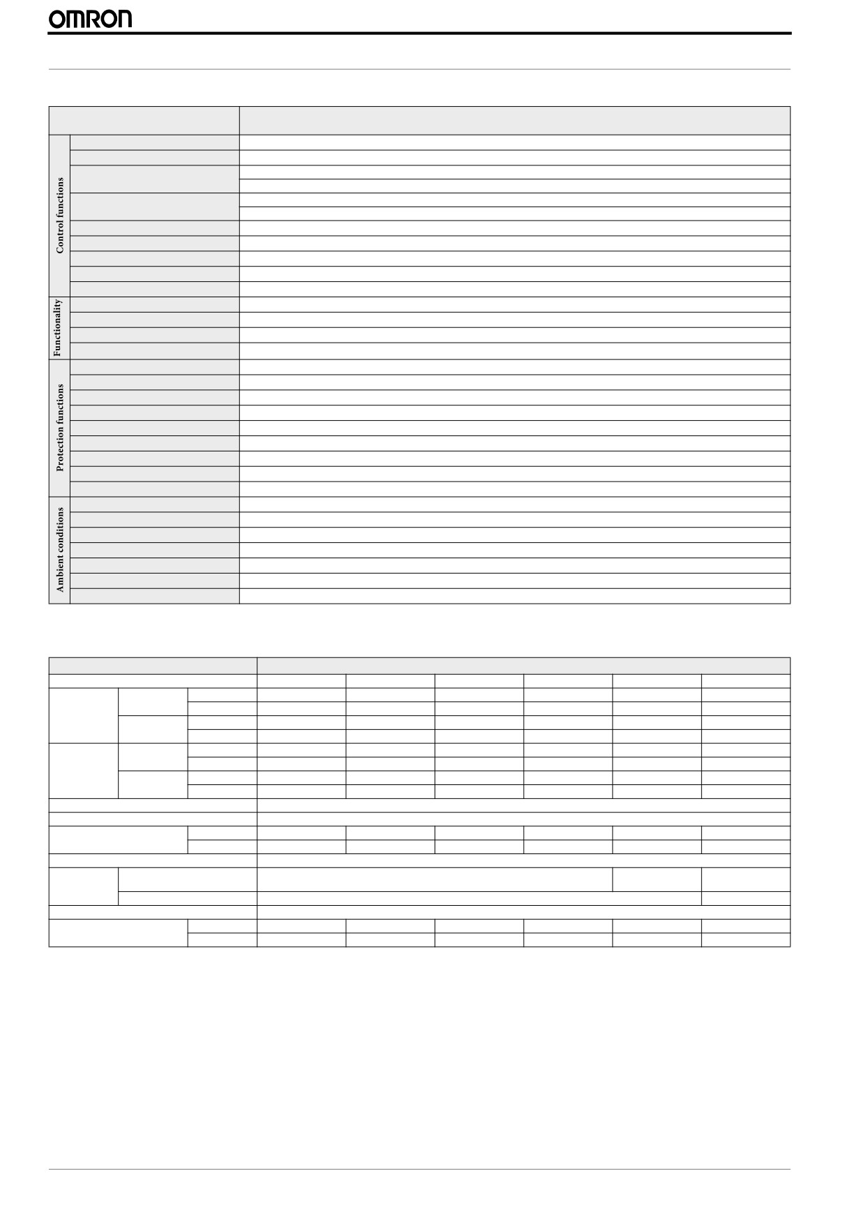
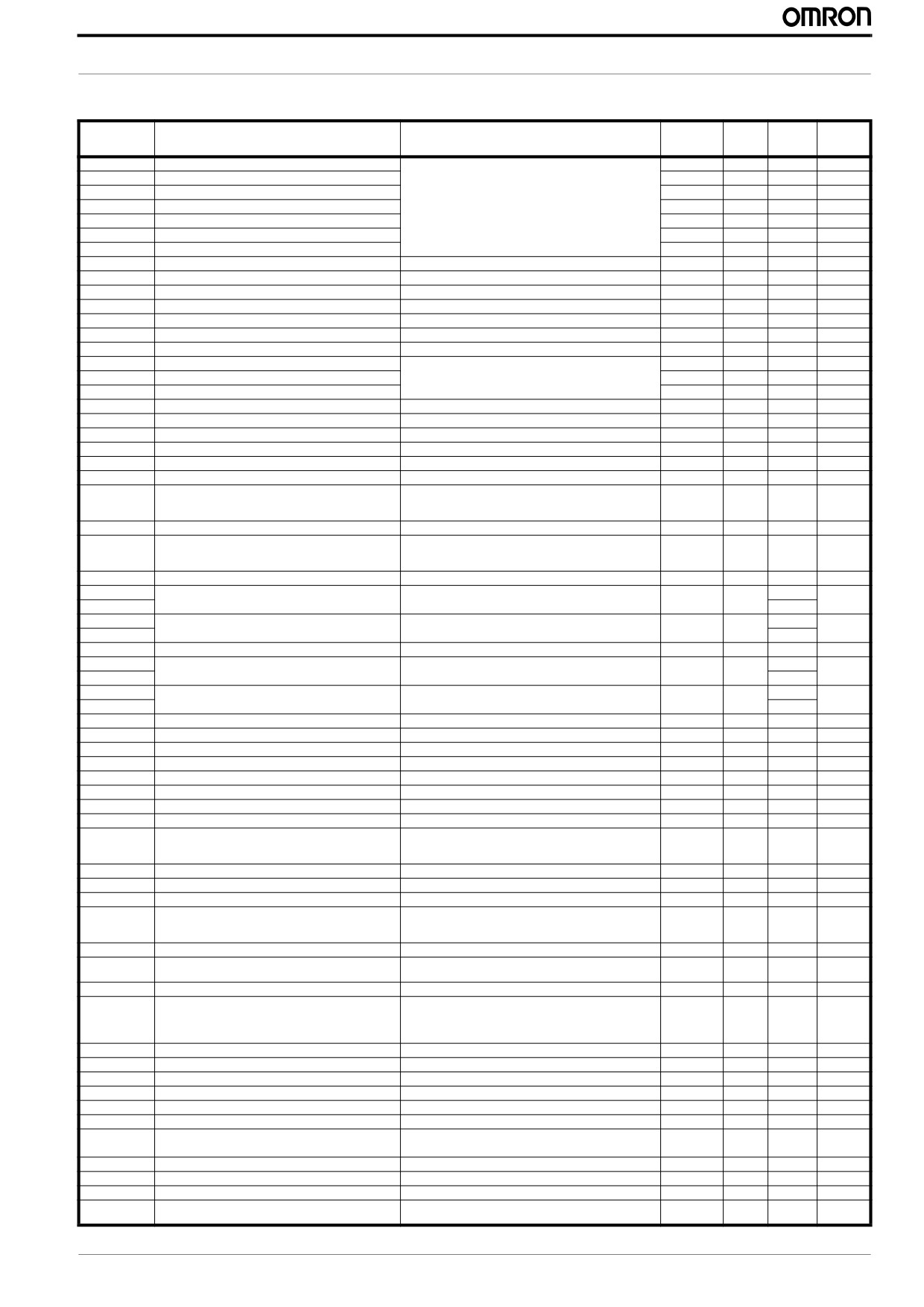
1.2 Technical specification
Model number
Specifications
MX2
Control methods
Phase-to-phase sinusoidal pulse with modulation PWM (Sensorless vector control, V/F)
Output frequency range
0.10..1000.00 Hz (with restrictions above 400Hz)
Digital set value: ±0.01% of the max. frequency
Frequency precision
Analogue set value: ±0.2% of the max. frequency (25 ±10 ºC)
Digital set value: 0.01 Hz
Resolution of frequency set value
Analogue set value: 1/1000 of maximum frequency
Resolution of output frequency
0.01Hz
Starting torque
200% / 0.5Hz
Overload capability
Dual rating: Heavy duty (CT): 150% for 1 minute
/ Normal Duty (VT): 120% for 1 minute
Frequency set value
0 to 10 VDC (10KW), 4 to 20mA (100W), RS485 Modbus, Network options
V/f Characteristics
Constant/ reduced torque, free V/f
Analogue inputs
2 analogue inputs 0 to 10V (10KW), 4 to 20mA (100W)
Pulse train input terminal
0 to 10V (up to 24V), up to 32KHz
Accel/Decel times
0.01 to 3600.0s (line/curve selection), 2nd accel/decel setting available
Display
Status indicator LED’s Run, Program, Alarm, Power, Hz, Amps
Motor overload protection
Electronic Thermal overload relay and PTC thermistor input
Instantaneous overcurrent
200% of rated current
Overload
Dual rating: Heavy duty (CT): 150% for 1 minute
/ Normal Duty (VT): 120% for 1 minute
Overvoltage
800V for 400V type and 400V for 200V type
Undervoltage
345V for 400V type and 172.5V for 200V type
Momentary power loss
Following items are selectable: Alarm, decelerates to stop, decelerates to stop with DC bus controlled, restart
Cooling fin overheat
Temperature monitor and error detection
Stall prevention level
Stall prevention during acceleration/deceleration and constant speed
Ground fault
Detection at power-on
Degree of protection
IP20, Varnish coating on PCB & IP54 (For 3G3MX2-D@ type)
Ambient humidity
90% RH or less (without condensation)
Storage temperature
-20 ºC..+65 ºC (short-term temperature during transportation)
Ambient temperature
-10°C to 50°C (Output current derating could be necessary above 40ºC or depending on installation conditions)
Installation
Indoor (no corrosive gas, dust, etc.)
Installation height
Max. 1000 m
Vibration
5.9 m/s2 (0.6G), 10 to 55 Hz
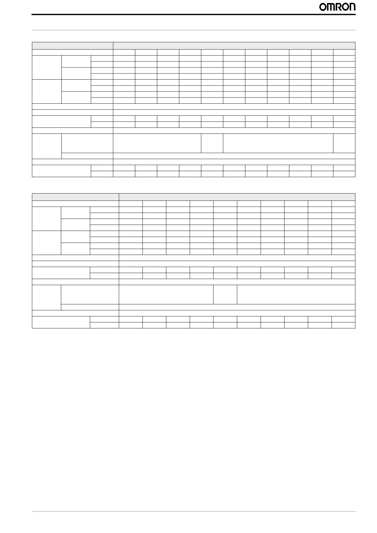
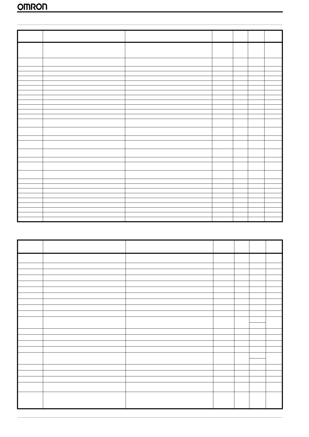
1.3 Power ratings
Item
Single-phase 200 V class Specifications
MX2 inverters, 200 V models
AB001
AB002
AB004
AB007
AB015
AB022
VT
0.2
0.4
0.55
1.1
2.2
3.0
kW
Applicable
CT
0.1
0.2
0.4
0.75
1.5
2.2
motor size
VT
1/4
1/2
3/4
1.5
3
4
HP
CT
1/8
1/4
1/2
1
2
3
VT
0.4
0.6
1.2
2.0
3.3
4.1
200 V
Rated capacity
CT
0.2
0.5
1.0
1.7
2.7
3.8
(kVA)
VT
0.4
0.7
1.4
2.4
3.9
4.9
240 V
CT
0.3
0.6
1.2
2.0
3.3
4.5
Rated input voltage
Single-phase: 200 V-15% to 240 V+10%, 50/60 Hz±5%
Rated output voltage
3-phase: 200 to 240 V (proportional to input voltage)
VT
1.2
1.9
3.5
6.0
9.6
12.0
Rated output current (A)
CT
1.0
1.6
3.0
5.0
8.0
11.0
Starting torque
200% at 0.5 Hz
100%: at50 Hz
70%: at 50 Hz
20%: at 50 Hz
Without resistor
Braking
50%: at 60 Hz
50%: at 60 Hz
20%: at 60 Hz
With resistor
150%
100%
DC braking
Variable operating frequency, time, and braking force
kg
1.0
1.0
1.1
1.4
1.8
1.8
Weight
lb
2.2
2.2
2.4
3.1
4.0
4.0
4
MX2 Quick Start Guide Draft
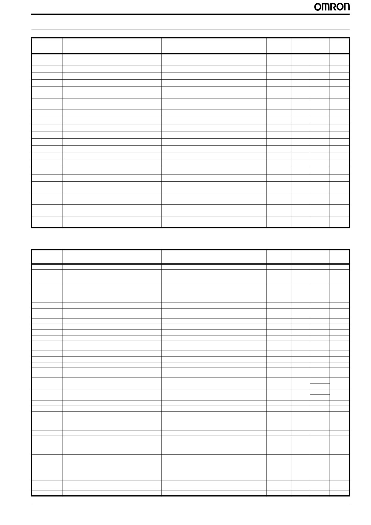
SPECIFICATIONS
Item
Three-phase 200V class Specifications
MX2 inverters, 200 V models
A2001
A2002
A2004
A2007
A2015
A2022
A2037
A2055
A2075
A2110
A2150
VT
0.2
0.4
0.75
1.1
2.2
3.0
5.5
7.5
11
15
18.5
kW
Applicable
CT
0.1
0.2
0.4
0.75
1.5
2.2
3.7
5.5
7.5
11
15
motor size
VT
1/4
1/2
1
1.5
3
4
7.5
10
15
20
25
HP
CT
1/8
1/4
1/2
1
2
3
5
7.5
10
15
20
VT
0.4
0.6
1.2
2.0
3.3
4.1
6.7
10.3
13.8
19.3
23.9
200 V
Rated
CT
0.2
0.5
1.0
1.7
2.7
3.8
6.0
8.6
11.4
16.2
20.7
capacity (kVA)
VT
0.4
0.7
1.4
2.4
3.9
4.9
8.1
12.4
16.6
23.2
28.6
240 V
CT
0.3
0.6
1.2
2.0
3.3
4.5
7.2
10.3
13.7
19.5
24.9
Rated input voltage
Three-phase: 200 V-15% to 240 V+10%, 50/60 Hz±5%
Rated output voltage
Three-phase: 200 to 240 V (proportional to input voltage)
VT
1.2
1.9
3.5
6.0
9.6
12.0
19.6
30.0
40.0
56.0
69.0
Rated output current (A)
CT
1.0
1.6
3.0
5.0
8.0
11.0
17.5
25.0
33.0
47.0
60.0
Starting torque
200% at 0.5 Hz
70%: at
100%: at
100%: at 50 Hz
50 Hz
100%: at 50 Hz
50 Hz
Without resistor
Braking
50%: at 60 Hz
50%: at
50%: at 60 Hz
50%: at
60 Hz
60 Hz
With resistor
150%
DC braking
Variable operating frequency, time, and braking force
kg
1.0
1.0
1.1
1.2
1.6
1.8
2.0
3.3
3.4
5.1
7.4
Weight
lb
2.2
2.2
2.4
2.6
3.5
4.0
4.4
7.3
7.5
11.2
16.3
Item
Three-phase 400V class Specifications
MX2 inverters, 400 V models
A4004
A4007
A4015
A4022
A4030
A4040
A4055
A4075
A4110
A4150
VT
0.75
1.5
2.2
3.0
4.0
5.5
7.5
11
15
18.5
kW
Applicable
CT
0.4
0.75
1.5
2.2
3.0
4.0
5.5
7.5
11
15
motor size
VT
1
2
3
4
5
7.5
10
15
20
25
HP
CT
1/2
1
2
3
4
5
7.5
10
15
20
VT
1.3
2.6
3.5
4.5
5.7
7.3
11.5
15.1
20.4
25.0
380 V
Rated capacity
CT
1.1
2.2
3.1
3.6
4.7
6.0
9.7
11.8
15.7
20.4
(kVA)
VT
1.7
3.4
4.4
5.7
7.3
9.2
14.5
19.1
25.7
31.5
480 V
CT
1.4
2.8
3.9
4.5
5.9
7.6
12.3
14.9
19.9
25.7
Rated input voltage
Three-phase: 380 V-15% to 480 V+10%, 50/60 Hz±5%
Rated output voltage
Three-phase: 380 to 480 V (proportional to input voltage)
VT
2.1
4.1
5.4
6.9
8.8
11.1
17.5
23.0
31.0
38.0
Rated output current (A)
CT
1.8
3.4
4.8
5.5
7.2
9.2
14.8
18.0
24.0
31.0
Starting torque
200% at 0.5 Hz
70%: at
100% at 50 Hz
50 Hz
100%: at 50 Hz
Without resistor
Braking
50%: at 60 Hz
50%: at
50%: at 60 Hz
60 Hz
With resistor
150%
DC braking
Variable operating frequency, time, and braking force
kg
1.5
1.6
1.8
1.9
1.9
2.1
3.5
3.5
4.7
5.2
Weight
lb
3.3
3.5
4.0
4.2
4.2
4.6
7.7
7.7
10.4
11.5
MX2 Quick Start Guide Draft
5
MX2 Quick Start Guide
2 INSTALLATION
2.1 Wiring sizes and protection
Inverter rating
Wiring
Applicable equipment
(KW)
Inverter Model
Terminal
Tighttening
Fuse
VT
CT
Power Lines (mm2)
Signal Lines
screw
Toque (N/m)
(UL-rated, class J, 600 V)
0.2
0.1
3G3MX2-AB001
0.4
0.2
3G3MX2-AB002
AWG16 / 1.3 mm²
M4
1.0
10 A
0.55
0.4
3G3MX2-AB004
1.1
0.75
3G3MX2-AB007
AWG12 / 3.3 mm²
M4
1.4
15 A
2.2
1.5
3G3MX2-AB015
20 A
AWG10 / 5.3 mm²
M4
1.4
3.0
2.2
3G3MX2-AB022
30 A
0.2
0.1
3G3MX2-A2001
0.4
0.2
3G3MX2-A2002
10 A
AWG16 / 1.3 mm²
M4
1.0
0.75
0.4
3G3MX2-A2004
1.1
0.75
3G3MX2-A2007
15 A
2.2
1.5
3G3MX2-A2015
AWG14 / 2.1 mm²
M4
1.4
3.0
2.2
3G3MX2-A2022
AWG12 / 3.3 mm²
M4
1.4
20 A
5.5
3.7
3G3MX2-A2037
AWG10 / 5.3 mm²
M4
1.4
18 to 28 AWG
30 A
7.5
5.5
3G3MX2-A2055
0.14 to 0.75 mm²
AWG6 / 13 mm²
M5
3.0
11
7.5
3G3MX2-A2075
shielded wire
40 A
15
11
3G3MX2-A2110
AWG4 / 21 mm²
M6
3.9 to 5.1
60 A
18.5
15
3G3MX2-A2150
AWG2 / 34 mm²
M8
5.9 to 8.8
80 A
0.75
0.4
3G3MX2-A4004
1.5
0.75
3G3MX2-A4007
AWG16 / 1.3 mm²
M4
1.4
10 A
2.2
1.5
3G3MX2-A4015
3.0
2.2
3G3MX2-A4022
AWG14 / 2.1 mm²
M4
1.4
4.0
3.0
3G3MX2-A4030
5.5
4.0
3G3MX2-A4040
A
WG12 / 3.3 mm²
M4
1.4
15 A
7.5
5.5
3G3MX2-A4055
AWG10/ 5.3 mm²
M5
3.0
11
7.5
3G3MX2-A4075
20 A
15
11
3G3MX2-A4110
30 A
AWG6 / 13 mm²
M6
3.9 to 5.1
18.5
15
3G3MX2-A4150
40 A
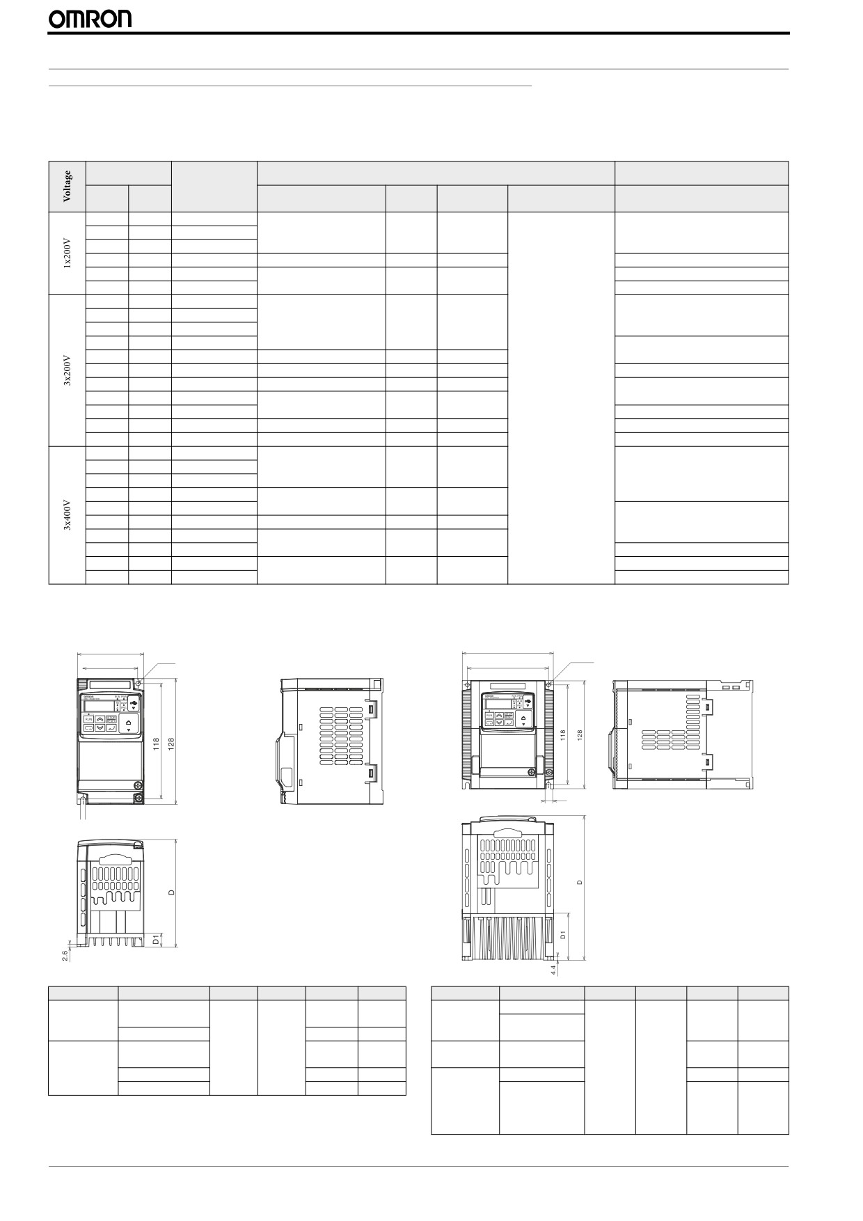
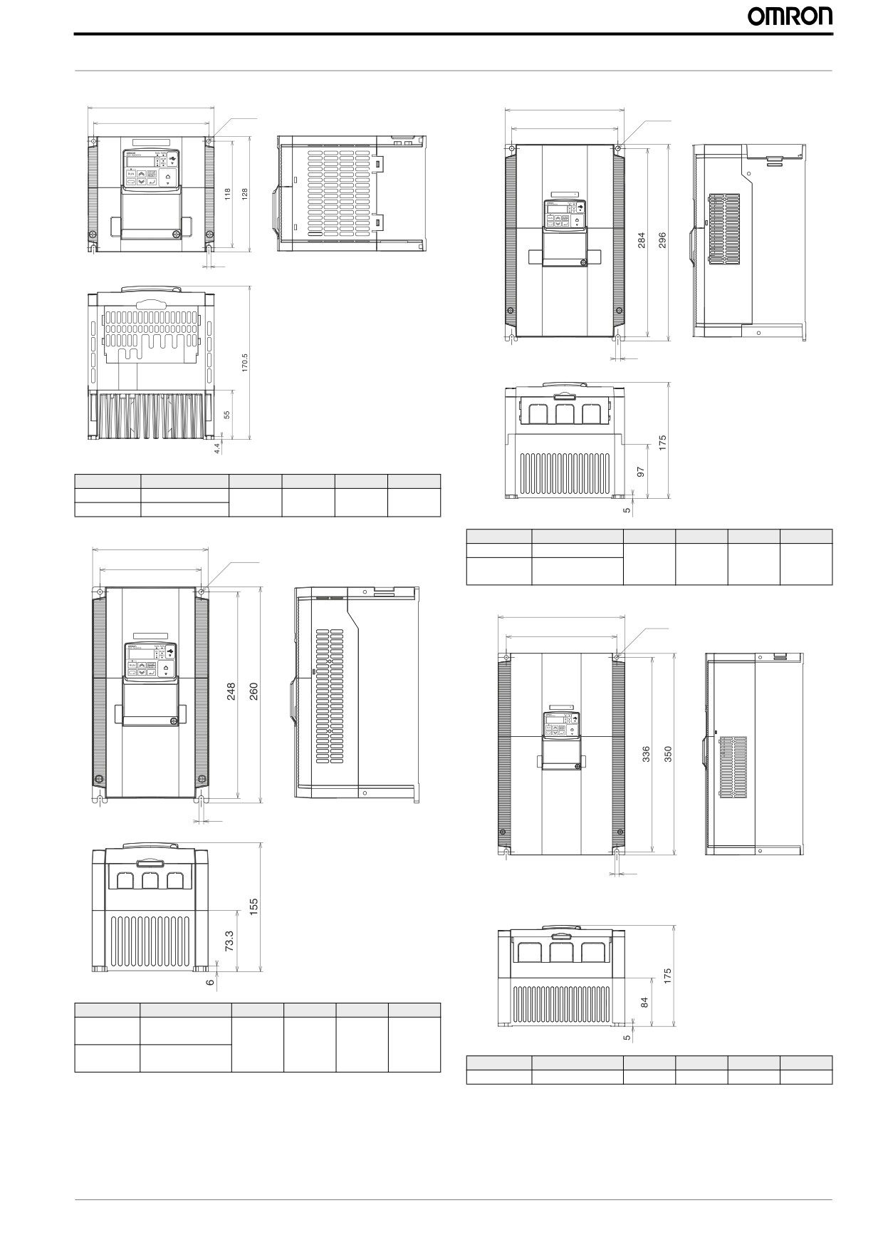
2.2 External dimensions for installation (IP20 & IP54)
68
108
Ø4.5
2-Ø4.5
56
96
8.8.8.8.
8.8.8.8.
5
5
Power
Type
W (mm) H (mm)
D (mm)
D1 (mm)
Power
Type
W(mm)
H (mm)
D (mm)
D1(mm)
3G3MX2-AB001
3G3MX2-AB007
109
13.5
1x 200V
3G3MX2-AB002
1x 200 V
3G3MX2-AB015
170.5
55
3G3MX2-AB004
122.5
27
3G3MX2-AB022
3G3MX2-A2001
68
128
3G3MX2-A2015
109
13.5
3x 200 V
170.5
55
3G3MX2-A2002
3G3MX2-A2022
3x 200 V
108
128
3G3MX2-A2004
122.5
27
3G3MX2-A4004
143.5
28
3G3MX2-A2007
145.5
50
3G3MX2-A4007
3x 400V
3G3MX2-A4015
170.5
55
3G3MX2-A4022
3G3MX2-A4030
6
MX2 Quick Start Guide Draft
INSTALLATION
140
180
2-Ø4.5
2-Ø7
128
160
8.8.8.8.
8.8.8.8.
5
7
Power
Type
W(mm)
H (mm)
D (mm)
D1(mm)
3x 200 V
3G3MX2-A2037
140
128
170,5
55
3x 400 V
3G3MX2-A4040
Power
Type
W(mm)
H (mm)
D (mm)
D1(mm)
140
3x 200 V
3G3MX2-A2110
2-Ø6
122
3G3MX2-A4110
180
296
175
97
3x 400 V
3G3MX2-A4150
220
2-Ø7
192
8.8.8.8.
8.8.8.8.
6
7
Power
Type
W(mm)
H (mm)
D (mm)
D1(mm)
3G3MX2-A2055
3x 200 V
3G3MX2-A2075
140
260
155
73.3
3G3MX2-A4055
3x 400 V
3G3MX2-A4075
Power
Type
W(mm)
H (mm)
D (mm)
D1(mm)
3 x 200 V
3G3MX2-A2150
220
350
175
84
MX2 Quick Start Guide Draft
7
MX2 Quick Start Guide
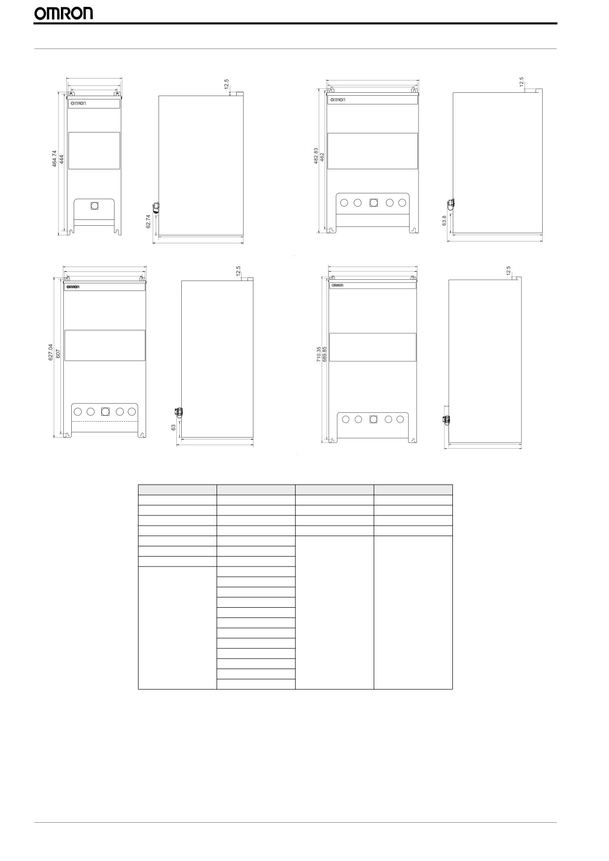
IP54
179.5
Figure 1
309.5
Figure 2
169.5
299.5
279.5
150
298.9
274
292.7
317.7
325
378.8
315
Figure 3
376.2
Figure 4
295
349
18.7
281
320.53
299.5
334.7
Figure 1
Figure 2
Figure 3
Figure 4
3G3MX2-DB001-E
3G3MX2-DB001-EC
3G3MX2-D2055-EC
3G3MX2-D2110-EC
3G3MX2-DB002-E
3G3MX2-DB002-EC
3G3MX2-D2075-EC
3G3MX2-D2150-EC
3G3MX2-DB004-E
3G3MX2-DB004-EC
3G3MX2-D4055-EC
3G3MX2-D4110-EC
3G3MX2-D2001-E
3G3MX2-DB007-EC
3G3MX2-D4075-EC
3G3MX2-D4150-EC
3G3MX2-D2002-E
3G3MX2-DB015-EC
3G3MX2-D2004-E
3G3MX2-DB022-EC
3G3MX2-D2007-E
3G3MX2-D2001-EC
3G3MX2-D2002-EC
3G3MX2-D2004-EC
3G3MX2-D2007-EC
3G3MX2-D2015-EC
3G3MX2-D2022-EC
-
3G3MX2-D2037-EC
3G3MX2-D4004-EC
3G3MX2-D4007-EC
3G3MX2-D4015-EC
3G3MX2-D4022-EC
3G3MX2-D4030-EC
3G3MX2-D4040-EC
8
MX2 Quick Start Guide Draft
INSTALLATION
Chassis ground of
mounting plate
Chassis ground of
EMC filter
Power input to
EMC filter
DIN rail for
mounting options
Bracket with
EMC filter
Fuse for
cooling fan
MX2 inverter
Cooling fan
Dust filter
Wiring acces hole
Mounting plate
Air outlet
Front cover
Window for MX2
inverter display
Lock for
front cover
USB connector
(mini-B)
Panel hole for accessory
2.3 Installation Environment clearance
100 mm or more
Provide sufficient
space so that the top
Air flow
and bottom wiring
ducts, etc. will not
obstruct the flows of
cooling air.
Wall
50 mm or more
50 mm or more
100 mm or more
Side by side installation is possible but ambient temperature should not exceed 40ºC and for some cases carrier frequency and
output current should be derated. Please refer to MX2 user’s manuals for details.
MX2 Quick Start Guide Draft
9
MX2 Quick Start Guide
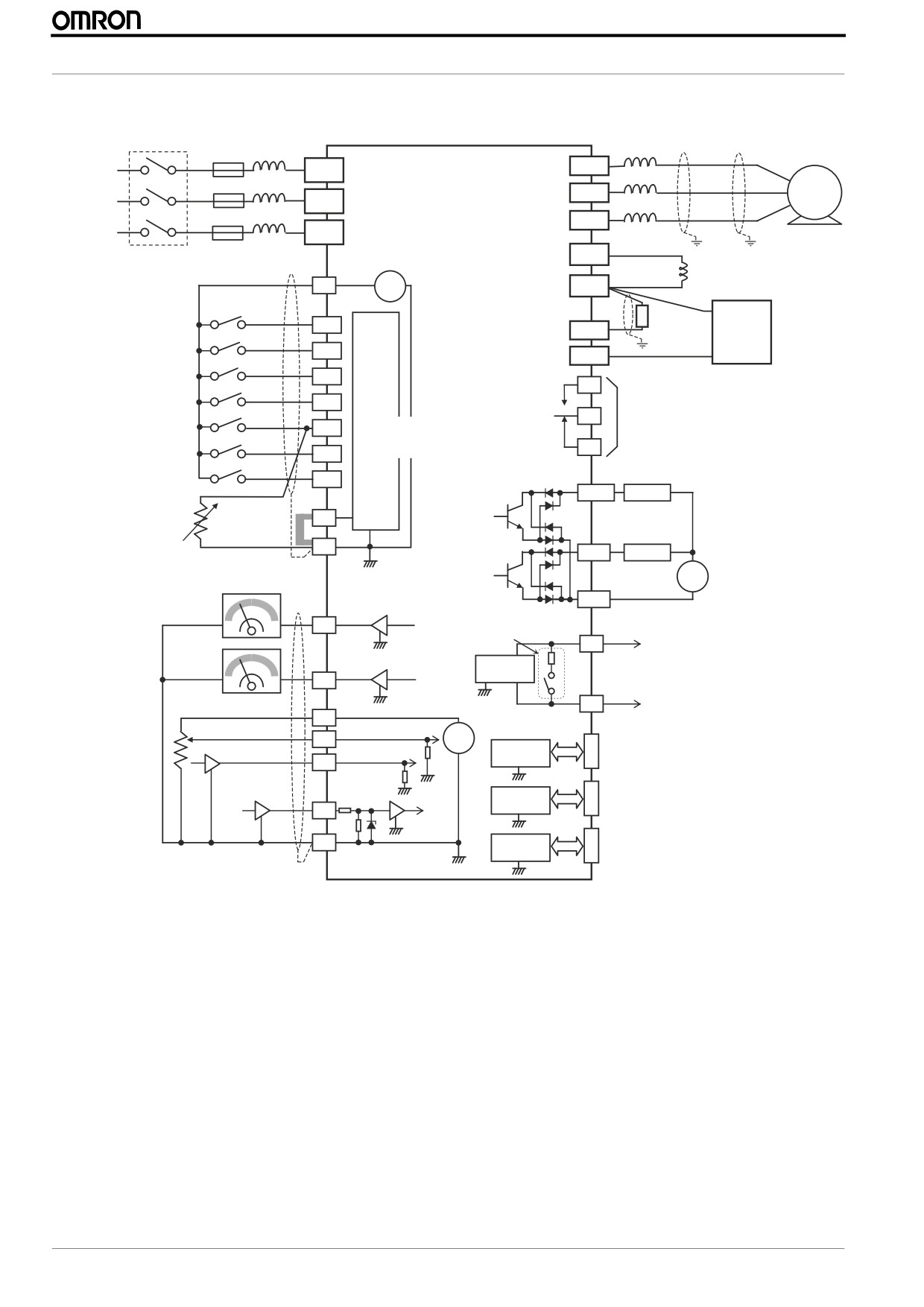
2.4 Wiring overview
Shielded motor cable
Breaker, MCCB
AC Reactor
Output
to minimize emitted EMC
or GFI,
dV/dt
Groudn both ends
Fuses
R
U (T1)
( L1 )
Motor
Power source,
MX2
3-phase or
V (T2)
S
1-phase, per
( L2 )
inverter model
W (T3)
T
N(L3)
PD/+1
DC reactor
Intelligent inputs,
24V
(optional)
7 terminals
P24
+ -
P/+
Forward
NOTE:
Brake
Braking
For the wiring of intelligent
1
RB
resistor
unit
I/O and analog inputs,
Reverse
(optional)
(optional)
be sure to use twisted
2
N/-
pair / shielded cable.
External Trip
Input
Attach the shielded wire
3/GS1
circuits
AL1
for each signal to its
Reset
Relay contacts,
respective common
4/GS2
type 1 Form C
terminal at the inverter
Multi-speed 1
AL0
end only.
[5] configurable as
5/PTC
Input impedance of
discrete input or
Multi-speed 2
each intelligent input is
thermistor input
AL2
6
4.7 kΩ
Open collector output
Jog
Output circuit
RUN
7/EB
11/EDM
Load
Thermistor
Short bar
PLC
(Source type)
Freq. arrival signal
L
12
Load
GND for logic inputs
L
+
-
Freq. Meter
CM2
Termination resistor (200 Ω)
Common for logic outputs
EO
(Change by slide switch)
L
SP
Volt. Meter
RS485
Serial communication port
transceiver
(RS485/ModBus)
AM
transceiver
L
L
SN
Analog reference
10 VDC
H
0~10VDC
+
O
RJ45 port
Apprx.10 Ω
-
RS485
4~20mA
(Optional operator port)
OI
transceiver
Pulse train input
Apprx.100 Ω
L
USB (mini-B) port
24 VDC 32 kHz max.
L
USB
(PC communication port)
transceiver
EA
USB power: Self power
L
L
L
Option port
Option port connector
GND for analog signals
controller
L
L
10
MX2 Quick Start Guide Draft
INSTALLATION
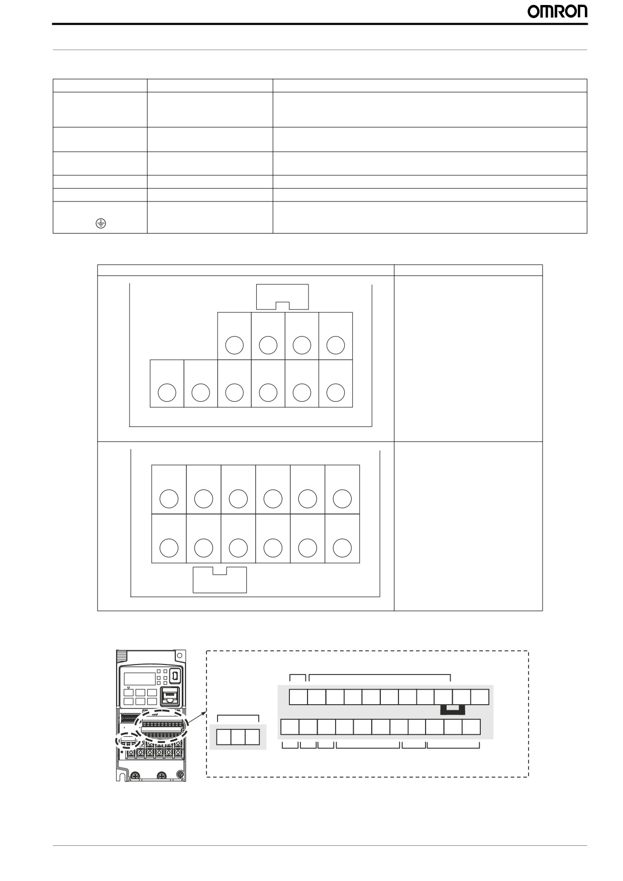
2.5 Power wiring
Terminal name
Purpose
Details
R, S, T
Main circuit, power supply
Single phase 200-240V (Connect to L1 and N terminals)
(L1, L2, L3)
Three phase 200-240V
Three phase 380-480V
U, V, W
Motor output
Three phase motor connection (IM, PM)
(T1, T2, T3)
+1, +
DC reactor
Remove the link and install DC reactor for improvement of harmonics level and
power factor
RB
Extrenal brake resistor
An external braking resistor is connected.
+, -
Regeneration braking unit
For connection of external regeneration braking unit
G
Earth
Earthing terminal.
Terminals arrangment
Applicable models
3G3MX2-AB001 to AB022
WR OLQN
5HPRYH IRU '&
3G3MX2-A2001 to A2037
UHDFWRU FRQQHFWLRQ
3G3MX2-A4004 to A4040
5%
5 /
6 /
7 /
8 7
9 7
: 7
3G3MX2-A2040 to A2150
3G3MX2-A4055 to A4150
5 /
6 /
7 /
8 7
9 7
: 7
5%
WR OLQN
5HPRYH IRU '&
UHDFWRU FRQQHFWLRQ
2.6 Control wiring
RS485
comm.
Logic inputs
Relay
SN
7
6
5
4
3
2
1
L
PLC
P24
contacts
Short bar
SP EO
EA
H
O
OI
L
AM CM2 12
11
AL2 AL1 AL0
RS485
Pulse
Pulse
Analog
Analog
Logic
Train
Train
output
comm.
input
output
onput
input
MX2 Quick Start Guide Draft
11
MX2 Quick Start Guide
Type
Terminal Name
Purpose
Details
Electrical specifications
P24
+24 V for logic inputs
24VDC power supply for the DI
Max 100mA including DI (5mA
When source logic is selected, it becomes the common
each)
point of input
(do not short to terminal L)
PLC
Intelligent input common
This terminal is used as the common terminal of the DI.
Power
For internal supply (and voltage-free contacts):
supply
Short between P24 and PLC: Sink logic (the current will flow from the MX2 input to the
output)
Short between CM1 and PLC: Source logic (the current will flow from the output to the
MX2 input)
L (upper row)
GND for logic inputs
Sum of input [1]~[7] currents (return)
1
Discrete logic inputs
It is possible to allocate any of the digital multifunction
ON voltage: 18V min
(Terminal [3],[4],[5] and [7] have dual function)
inputs to this terminals.
OFF voltage: 3V max
2
When safety function is enable by hardware dip-switch
Max.voltage: 27 VDC
multifunction setting 77:GS1 amd 78:GS2 are compul-
3/GS1
Load current: 5mA at 24V
sory for terminals 3 and 4 and functionality change
based on ISO13849-1
4/GS2
For PTC connect the motor thermistor between termi-
Input
5/PTC
nals 5 and L and assign 19:PTC on parameter C005.
Inverter will trip when thermistor exceed 3kOhm.
6
For pulse train input B set 85:EB in C007 parameter.
Max freq for this terminal is 2kHz.
7/EB
EA
Pulse train input A
32 kHz max.
Common is [L]
11/EDM
Discrete logic outputs [11]
Any multifunction output signal can be set to this ter-
50mA max. ON state current,
(Terminal [11] has dual function. Selected by
minals.
27 VDC max. OFF voltage
hardware switch)
In case the EDM is selected, the functionality is based
on ISO13849-1
12
Discrete logic outputs [12]
50 mA max. ON state current, 27 VDC max. OFF state voltage
Common is CM2
CM2
GND for logic output
100 mA: [11], [12] current return
Output
EO
Pulse train output
10 VDC 32 kHz maximum
2mA maximum
AL0
Relay common contact
Any multifunction output signal can be set to this ter-
250 VAC 2.5 A(R load) max.
minals.
250 VAC 0.2 A (I load,P.F.=0.4)
AL1
Relay contact, normally open
100 VAC 10 mA min.
AL2
Relay contact, normally closed
30 VDC 3.0 A(R load) max.
30 VDC 0.7 A(I load, P.F.=0.4)
5 VDC 100 mA min
Output AM
Analog voltage output
0~10 VDC
1 mA maximum
OI
Analog current input
4 to 19.6 mA range, 20 mA nominal,
input impedance 100 W
Input
O
Analog voltage input
0 to 9.8 VDC range, 10 VDC nominal,
input impedance 10 KW
+10 V analog reference
10 VDC nominal, 10 mA max
Power
H
supply L (bottom row)
GND for analog signals
Sum of [OI], [O], and [H] currents (return)
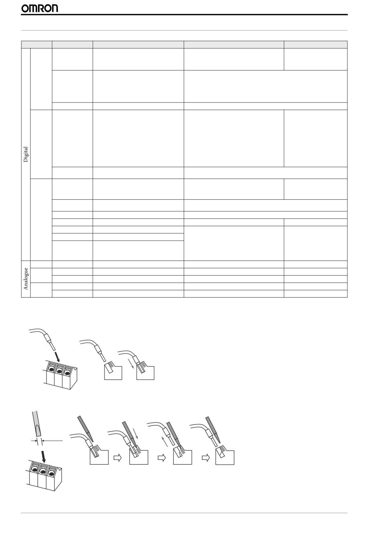
2.7 Screwless terminals connection
To connect cable, just push the terminal into position
To release cable, press the orange tab with small screwdriver and remove the cable
2.5 mm
Push the screwdriver
Pull out the cable
Release the
screwdriver
12
MX2 Quick Start Guide Draft
INSTALLATION
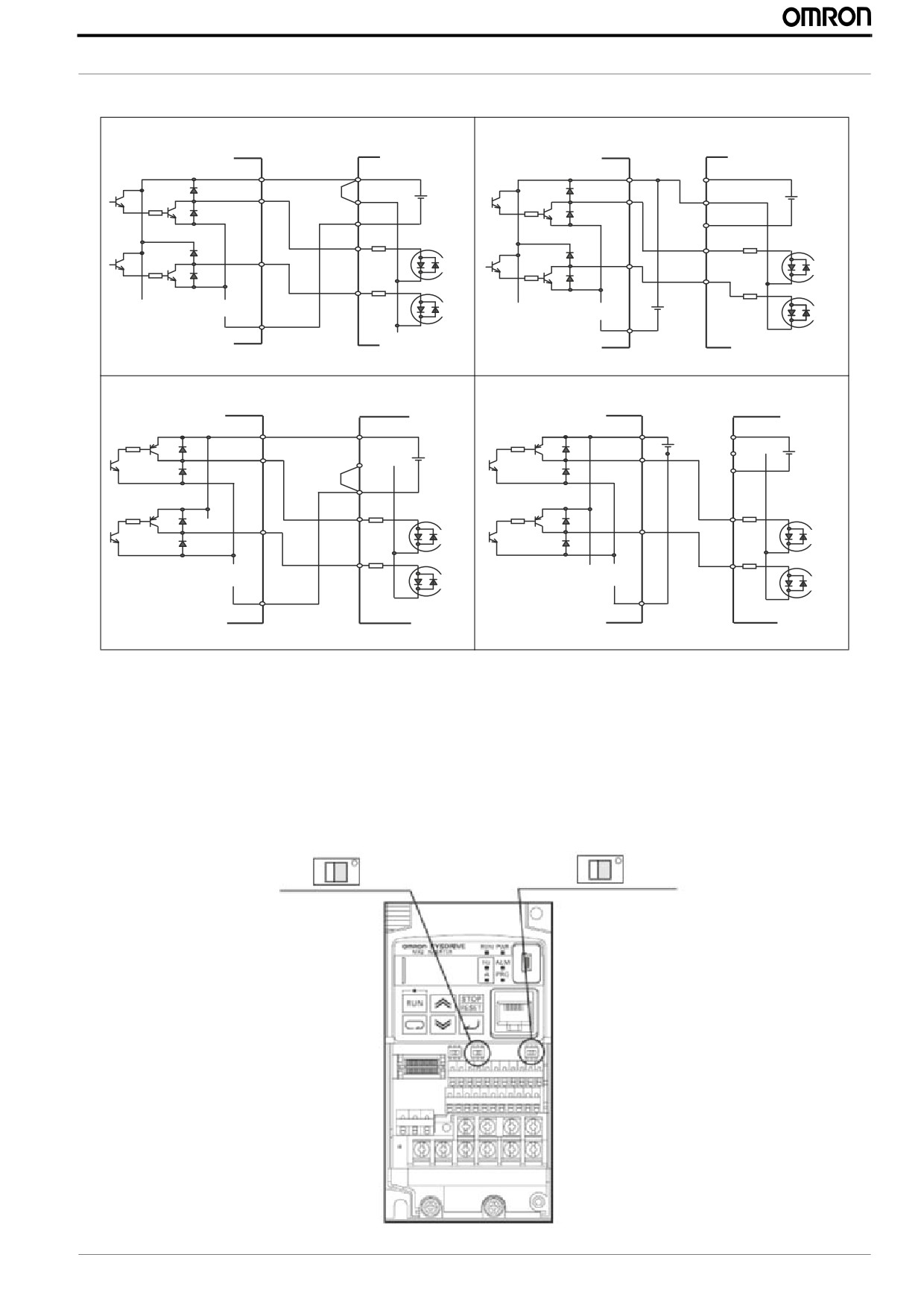
2.8 Digital inputs SINK/SOURCE (NPN/PNP) settings
Sinking internal supply
Sinking external supply
(for NPN outputs)
(for NPN outputs
+V
P24
+V
P24
Short-circuit
PLC
PLC
bar
24 V DC
24 V DC
L
L
1
1
7
7
COM
DC24V
COM
Output unit etc.
Output unit etc.
Inverter
Inverter
Sourcing internal supply
Sourcing external supply
(for PNP outputs)
(for PNP outputs
COM
P24
P24
COM
24 V DC PLC
Short-circuit
PLC
24 V DC
L
24 V DC
bar
L
1
1
7
7
0V
0V
Output unit etc.
Output unit etc.
Inverter
Inverter
2.9 Safe stop disable function
MX2 inverter incorporates a SAFE STOP function at hardware level according with EN60204-1 stop category 0. It is designed to
meet the requirements of the ISO13849-1, PL=d and IEC61508 SIL 2 only in a system in which EDM signal is monitored by an
“external device monitor”. Two redundant inputs are required (3/GS1 and 4/GS2). The function is purely hardware based. but to
activate it you should set below switches to ON. This will fix the configuration of multi-function inputs 3 (C003=77) and 4
(C004=78) and also for the multi-function output 11 (C021=62).
When the switches are set to OFF the multi-function input and output the configuration is set to No function selection
6DIHW\ IXQFWLRQ VHOHFWRU VZLWFK
('0 IXQFWLRQ VHOHFWRU VZLWFK
2))
21
2))
21
QRUPDO
('0
MX2 Quick Start Guide Draft
13
MX2 Quick Start Guide
3 PROGRAMMING MX2
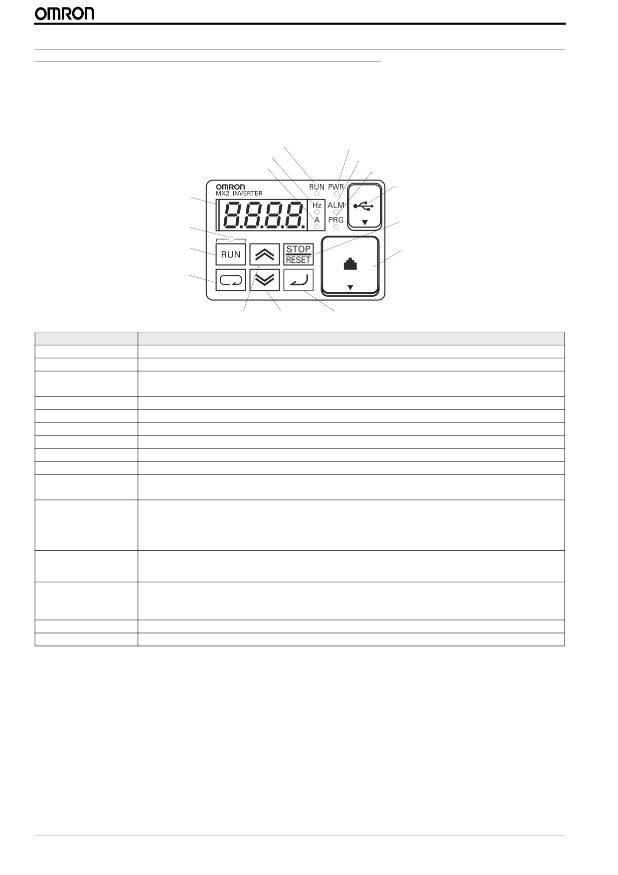
3.1 Digital operator
The display is used in programming the inverter's parameters, as well as monitoring specific parameter values during operation
(4) RUN LED
(1) POWER LED
(5) Monitor LED [Hz]
(2) ALARM LED
(6) Monitor LED [A]
(3) Program LED
(15) USB connector
(8) 7-seg LED
(7) Run command LED
(10) Stop/reset key
(9) RUN key
(16) RJ45 connector
(11) CYCLE key
(12) Up key
(13) Down key
(14) Set Key
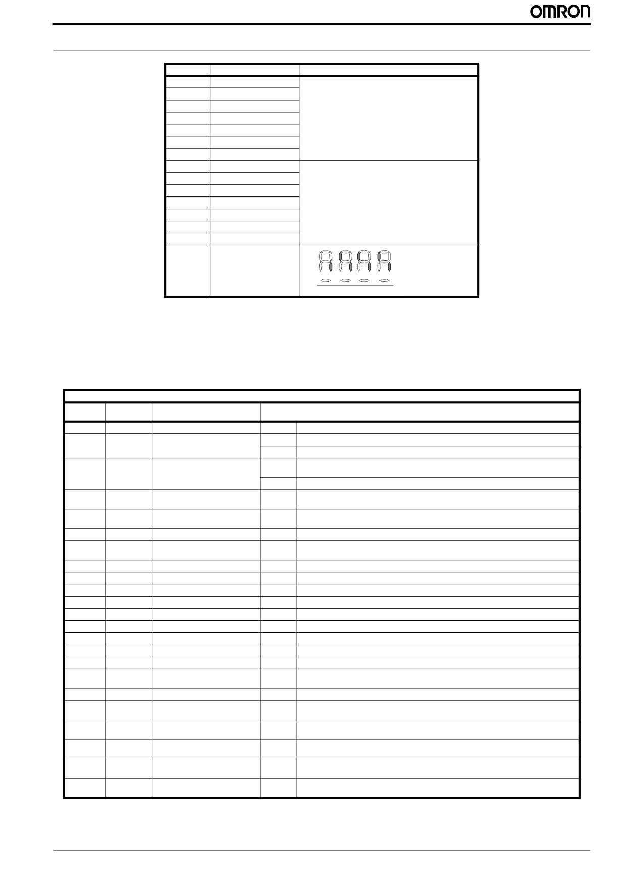
Items
Contents
(1) POWER LED
Turns ON (Green) while the inverter is powered up.
(2) ALARM LED
Turns ON (Red) when the inverter trips.
(3) Program LED
Turns ON (Green) when the display shows changeable parameter.
Blinks when there is a mismatch in setting.
(4) RUN LED
Turns ON (Green) when the inverter is driving the motor.
(5) Monitor LED [Hz]
Turns ON (Green) when the displayed data is frequency related.
(6) Monitor LED [A]
Turns ON (Green) when the displayed data is current related.
(7) Run command LED Turns ON (Green) when a Run command is set to the operator. (Run key is effective.)
(8) 7-seg LED
Shows each parameter, monitors etc.
(9) Run key
Makes inverter run.
(10) Stop/reset key
Makes inverter decelerates to a stop.
Reset the inverter when it is in trip situation
(11) CYCLE key
Go to the top of next function group, when a function mode is shown
Cancel the setting and return to the function code, when a data is shown
Moves the cursor to a digit left, when it is in digit-to-digit setting mode
Pressing for 1 second leads to display data of , regardless of current display.
(12) Up key
Increase or decrease the data.
Pressing the both keys at the same time gives you the digit-to-digit edit.
(13) Down key
(14) SET key
Go to the data display mode when a function code is shown
Stores the data and go back to show the function code, when data is shown.
Moves the cursor to a digit right, when it is in digit-to-digit display mode
(15) USB connector
Connect USB connector (mini-B) for using PC communication
(16) RJ45 connector
Connect RJ45 jack for remote operator
14
MX2 Quick Start Guide Draft
PROGRAMMING MX2
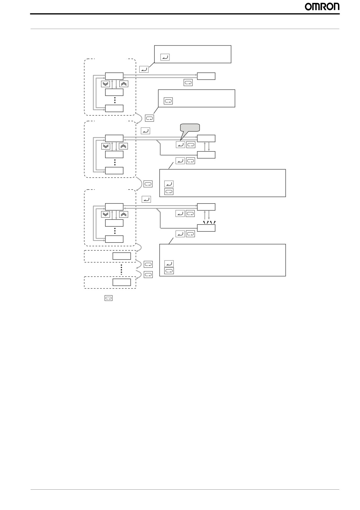
3.2 Keypad navigation
Func. code display
: Moves to data display
Group "d"
Func. code display
D001
0.00
D002
Func. code display
: Jumps to the next group
d104
Group "F"
Func. code display
Save
F001
50.00
F002
50.01
F004
Data display (F001 to F*03)
Data does not blink because of real time synchronizing
: Saves the data in EEPROM and returns to func. code display
Group "A"
: Returns to func. code display without saving data.
Func. code display
A001
00
A002
01
A165
Data display
When data is changed, the display starts blinking, which means that
Group "b"
b001
new data has not been activated yet.
: Saves the data in EEPROM and returns to func. code display
: Cancels the data change and returns to func. code display.
Group "U"
U001
Pressing
for a few seconds will return to the initial display
Pressing at the same time the up and down key in function code or data display will enable the single-digit edit mode that allows
a faster navigation, refer to the manual for more details.
3.3 Initialization
You can restore all inverter parameters to the original factory (default) settings according to area of use. After initializing the
inverter, use the power up test in Chapter 2 to get the motor running again. If operation mode (std. or high frequency) mode is
changed, inverter must be initialized to activate new mode. To initialize the inverter, follow the steps below.
• Select initialization mode in b084.
00 Initialization disable
01 Clears trip history
02 Initializes all Parameters
03 Clears Trip history and initializes all parameters
04 Clears Trip history and initializes all parameters and drive programming
• If =, or , select initialization target data in .
00 All parameters
01 All parameters except I/O configuration
02 Only parameters register in Uxxx
03 All parameter except the ones registered in Uxxx and b037
• Set
MX2 Quick Start Guide Draft
15
MX2 Quick Start Guide
The following display appears for a few seconds, and initialization is completed with d001 displayed
Display during initialization
5 HC
Initialization of trip history
Initialization
5 00
Initialization for area A
mode
5 01
Initialization for area B
The left digit rotates during initialization
d001
Blinking alternately
1-C
HD mode
Operation
mode after
1-V
ND mode
initialization
H-1
High frequency mode
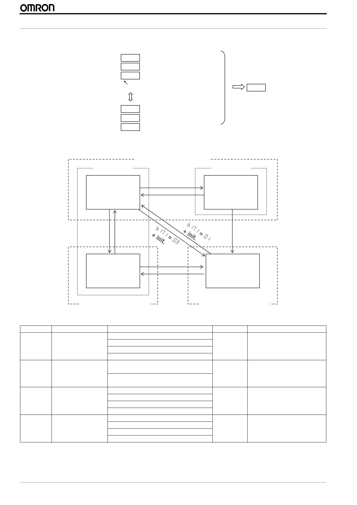
3.4 Inverter modes
Normal mode (㹼400 Hz)
HD mode
ND mode
HD mode
b049 = 01
ND mode
b049: 00
b049: 01
d060:
1-C
b049 = 00
d060:
1-v
b171 = 02
b171 = 01
b171 = 03
+ init.
+ init.
+ init.
b171 = 03
High freq. mode
+ init.
Permanent magnet
mode
d060: H-1
d060: P
b171 = 02
+ init.
High freq. (㹼1000 Hz)
Permanent magnet mode
Display code
Function name
Setting range/content
Initial value
Remarks
V/f characteristic curve
00: Constant torque
0
For the second motor use parame-
01: Reduced torque
ter A244
A044
02: Free V/F
03: Sensorless Vector Control
Dual rating selection
00: Constant torque
00
Some parameters default and
150% overload during 60s
ranges depends off this setting.
b049
01: V
ariable torque
Refer to below table for details
120% overload during 60s
Inverter mode selection
00: No function
00
To enable the new mode is neces-
01: Standard Induction Motor
sary to initialize the inverter
b171
02: High Frequency Induction Motor
03: Permanent Magnet Motor
Inverter mode monitor
IM-CT (Induction motor constant torque)
-
Displays the current inverter mode
IM-VT(Induction motor variable torque)
use this one to check configuration
d060
Hi-IM (High frequency induction motor)
as b171 returns to 0 after initialize
PM (Permanent magnet motor)
Neither the A044 or the b049 needs a initialization but remember to initialize the drive setting b180=01 when the inverter mode
is changed on b171.
16
MX2 Quick Start Guide Draft
PROGRAMMING MX2
This table shows the parameters that change with the dual rating selectiong is modified
Name
Func.
HD
ND
code
Range
initial data
Range
initial data
V/f characteristic curve
A044
00: Const. torque
00: Const. tq.
00: Const. torque
00: Const. tq.
01: Reduced torque
01: Reduced tq.
02: Free V/F
02: Free V/F
03: SLV
DC braking force for deceleration
A054
0 to 100 (%)
50 (%)
0 to 70 %
50 (%)
DC braking force at start
A057
0 to 100 (%)
0 (%)
0 to 70 %
0 (%)
Carrier frequency during DC braking A059
2.0 to 15.0(kHz)
5.0(kHz)
2.0 to 10.0(kHz)
2.0(kHz)
Overload restriction level
b022
(0.20 to 2.00)
1.50 x Rated current (0.20 to 1.50)
1.20 x Rated current
Overload restriction level 2
b025
x Rated current (A)
(A)
x Rated current (A)
(A)
Carrier frequency
b083
2.0 to 15.0(kHz)
5.0(kHz)
2.0 to 10.0(kHz)
2.0(kHz)
Motor capacity
H003
0.1 to 15(kW)
Depends on type
0.2 to 18.5(kW)
One size up than
HD
3.5 Basic settings
After selecting the inverter mode follow next steps for a basic operation of the inverter
•
Select frequency reference source on parameter A001
Parameter nº
Parameter Name
Details
00 Potentiometer of ext. operator
01 Control terminals
02 Digital operator (F001)
03 ModBus Network
A001
Frequency source
04 Option
06 Pulse train input
07 Via Drive programming
10 Calculate function output
•
Select Run command source on parameter A002
Parameter nº
Parameter Name
Details
01 Control terminals
02 Run key on keypad or digital operator
A002
Run command source
03 Modbus network input
04 Option
•
Adjust the stopping method by b091 and the acceleration/deceleration ramps on parameters F002 and F003
Parameter
Parameter Name
Details
00: Deceleration to stop
b091
Stop mode selection
01: Free Run
F002
Acceleration time (1)
0.01 to 3600.00
F003
Deceleration time(1)
0.01 to 3600.00
•
Set the motor base frequency and AVR voltage of the motors in parameters A003 and A082
Parameter
Parameter Name
Details
A003
Base Frequency
30.0 to maximum frequency in A004
200V: 200 to 240V
A082
AVR voltage select
400V: 380 to 480V
•
Set the motor data: rated current (b012), rated power (H003) and number of poles (H004)
Parameter
Parameter Name
Details
b012
Level of electronic thermal
20% to 100% of inverter rated current
H003
Motor capacity
0.1 to 18.5KW
H004
Motor poles settings
2 to 48 poles
•
When working in sensorless vector control perform motor auto tuning by parameter H001 (see next section for details)
MX2 Quick Start Guide Draft
17
MX2 Quick Start Guide
At this point the inverter is ready to run the motor for the first time, but first review this check-list:
• Verify the power LED is ON. If not, check the power connections.
• Verify the PRG LED is OFF. If it is ON, review the instructions above.
• Make sure the motor is disconnected from any mechanical load.
• Make sure that you have a frequency reference checking the content of F001 and the Hz Led on operator
• Now give the RUN command from the selected source. The RUN LED will turn ON.
• The motor should start turning.
• Remove the RUN command or press the STOP key to stop the motor rotation.
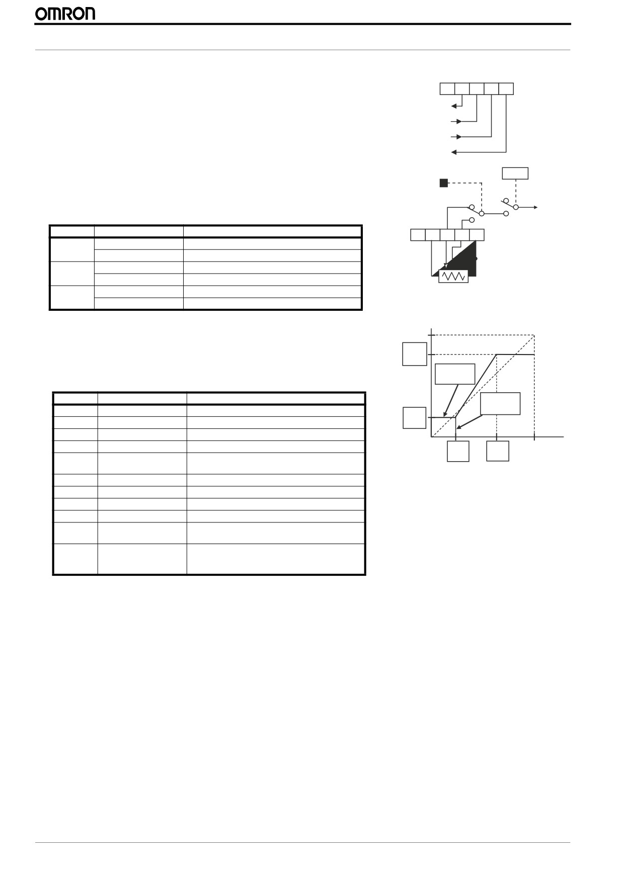
3.6 Auto tuning (SLV Mode)
The MX2 inverter has auto-tuning function to get suitable motor control performance by measuring the motor constants auto-
matically. Auto-tuning is effective only for sensorless vector control. Basically two modes are available the static and the rotative
one:
• Static is less accurate but it could be used in situations where motor rotation could damage the mechanics. For this mode nei-
ther the I0 (no-load current) or the J (inertia) are calculated.
• Rotative auto-tuning moves the motor following a special operation pattern to find the motor characteristics. However, the
torque during auto-tuning is not sufficient so is recommended to detach the mechanical system and don’t use for example
with vertical loads.
The Auto-tuning mode is selected by parameter H001 and after it finish succefully is necessary to to select the auto-tuning
parameters by parameter H002.
Parameter
Parameter Name
Description
00: Disable
H001
Auto-tuning selection
01: Enabled with motor stop
02: Enabled with motor rotation
00: Standard motor
H002
Motor constant selection
02: Auto tuned data
For a correct auto-tuning calculation please take into account following recommendations before starting:
• Use only a motor of the same size or one size lower than the inverter.
• Be sure to disable the DC braking setting (A051=00)
• Be sure to deactivate ATR digital input (52: Enable torque cmd. input)
• Motor rotates up to 80% of base frequency, check if it’s a problem for the application.
• Motor should not be driven by any other external force.
• All the brakes should be released
• Be sure that physical limtis of the machine will not be reach
• Even for none-rotative auto-tuning there is a risk that motor moves slightly
After checking the above points and setting parameter H001 procced with the activation of the Run command from the source
selected on A002 and the auto-tuning will start. Please check the diagram on next page for detailed information of all the steps.
After the tuning the H001 returns to “00” status and the motor characteristics are transferred to those parameter, remember to
set H002 to use them.
Parameter
Parameter Name
Description
H030
Motor constant R1
0.001 to 65.535 Ohms
H031
Motor constant R2
0.001 to 65.535 Ohms
H032
Motor constant L
0.01 to 655.35 mH
H033
Motor constant I0
0.01 to 655.35 A
H034
Motor constant J
0.001 to 9999 kgm2
Note: In case rotary tuning is not possible or autotuning results in very high No Load current (H033) (this is possible with small
motors), please use this formula to calculate theoretical value:
H033 = Inom * sin (arccos(cos phi)).
18
MX2 Quick Start Guide Draft
PROGRAMMING MX2
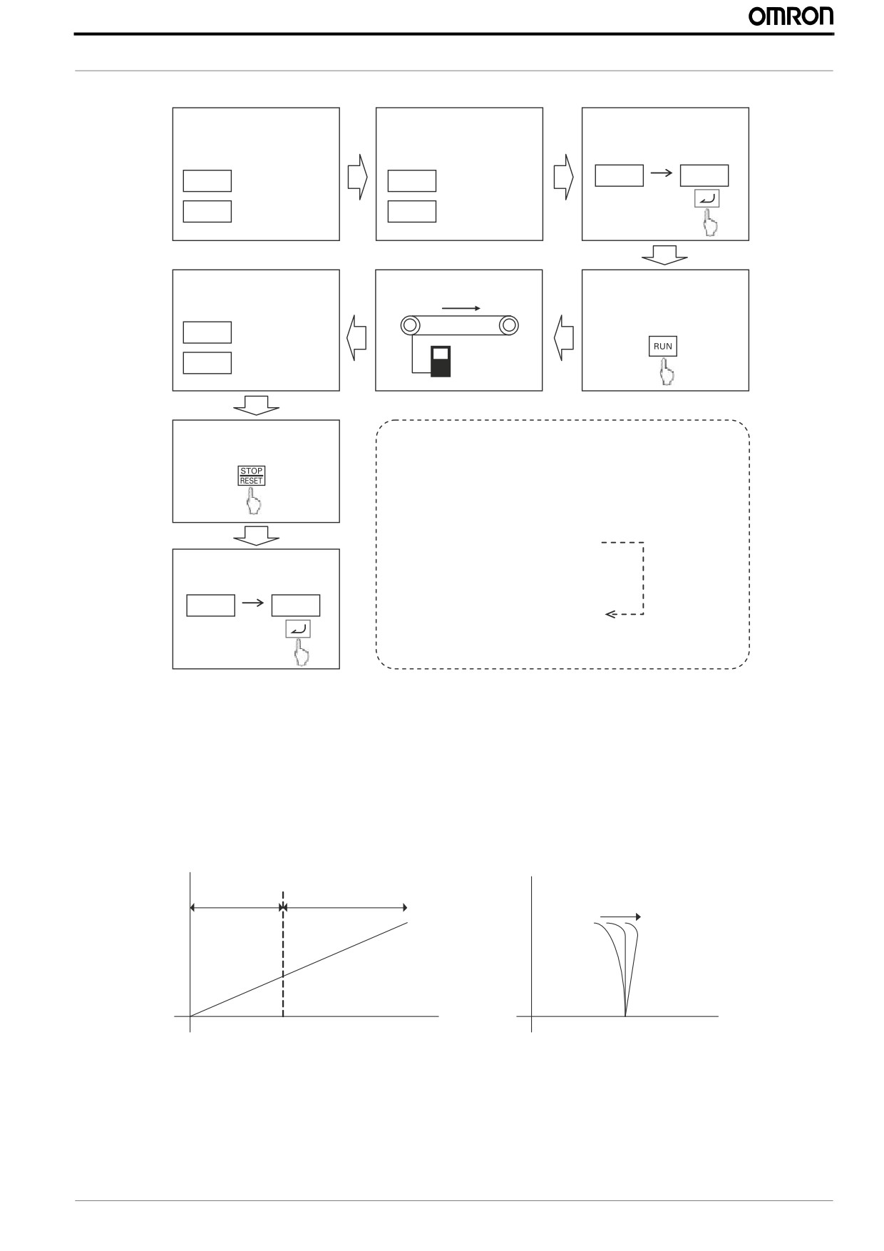
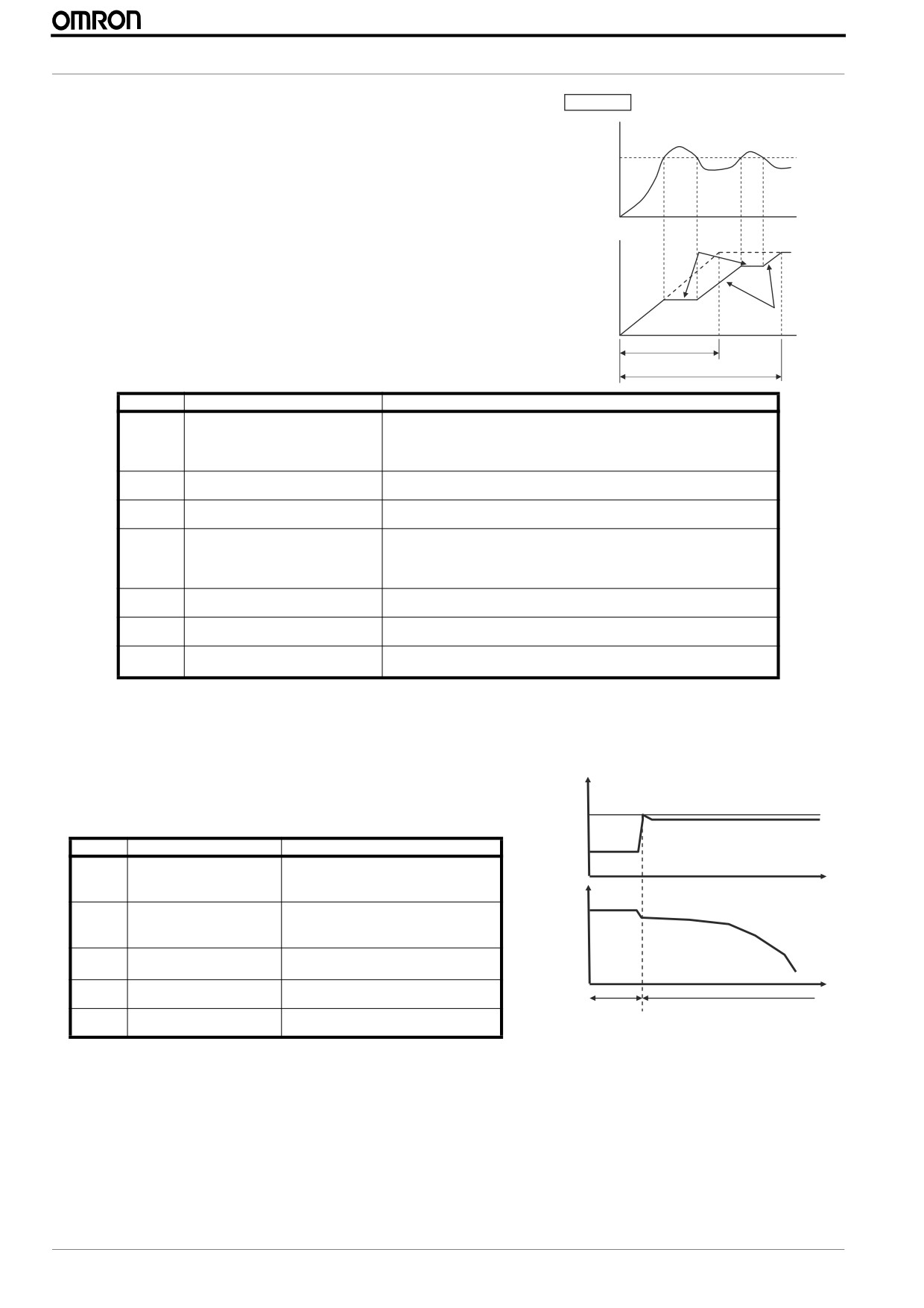
Next diagram shows the auto-tuning procedure with motor rotation
Step 1: Set motor size and
Step 2:Set base freq. and
Step 3: Enable auto-tuning
motor poles
AVR voltage
H001
02
H003
Motor size
A003
Base freq.
H004
Motor poles
A082
AVR voltage
Result is displayed
Auto-tuning starts
Step 4: Start the inverter
according to RUN
cmd source
___o
Completed
___9
Failed
Step 5: Clear display by
STOP key
When RUN cmd. is given, the motor runs according to
following steps.
(1) 1st AC excitation (no rotation)
(2) 2nd AC excitation (no rotation)
(3) 1st DC excitation (no rotation )
Step 6: Activate motor
(4) V/f operation (80% of base freq.)
constant by H002
(Note 1)
(5) SLV operation (X % of base freq.)
H002
02
(6) 2nd DC excitation (no rotation)
(7) Displays the result.
A fine tuning could be achived setting parameter H005 that adjust the motor speed response. If the motor vibrates at constant
speed then you should reduce the H005 setting, if on the contrary the response of the motor is not enough you could increase the
value.
The H005 acts as a global gain response but also is possible to adjust the motor response at certain areas adjusting the motor
parameters separately.
• The R1 parameter is adjusting the voltage applied at low speed, below 15-20Hz
• No load current I0 is used for adjusting the voltage above this 15-20Hz
• Finally R2 value is used to adjust the slip of the motor
No-load
V
current
R1
R2
15/20 Hz
Hz
Speed
MX2 Quick Start Guide Draft
19
MX2 Quick Start Guide
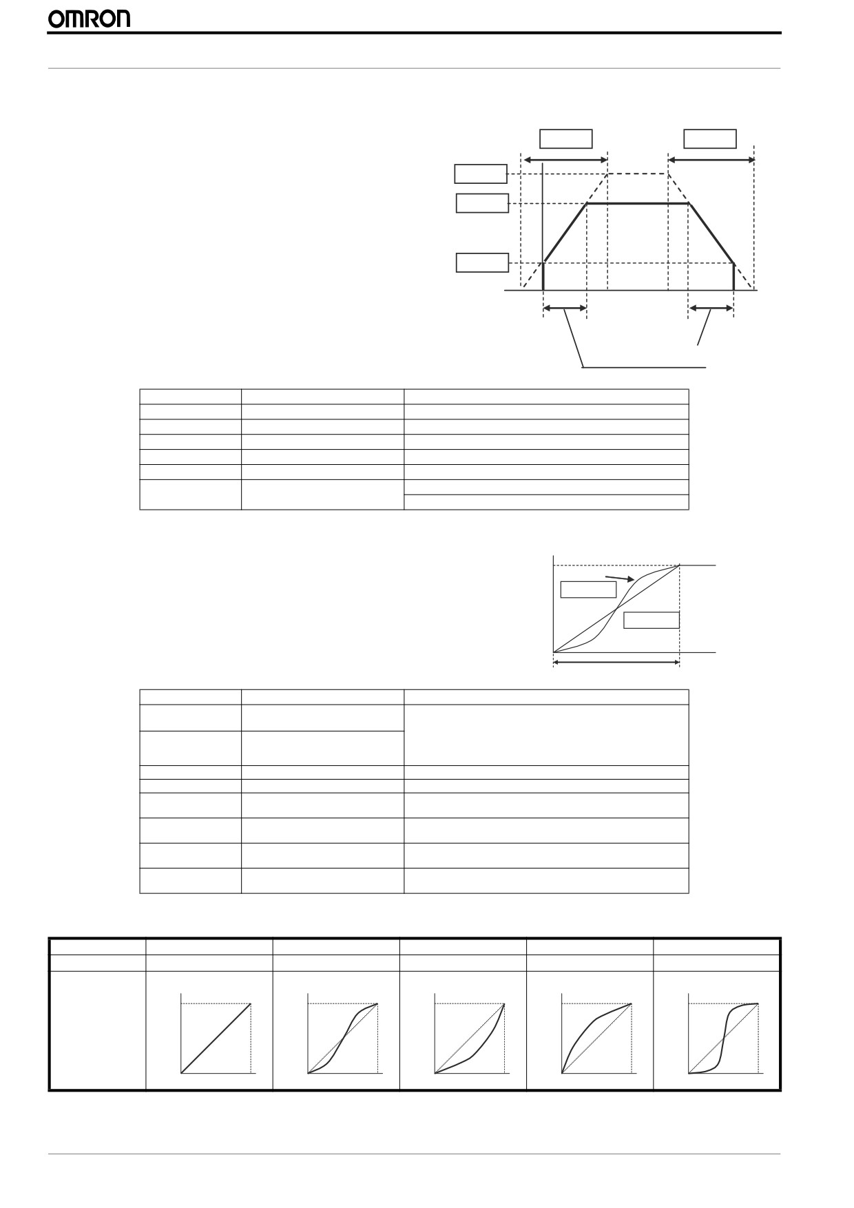
3.7 Ramps adjustment
The basic frequency (speed) profile is defined by parameters con-
Output
tained in the "F" Group as shown to the right. The set running fre-
frequency
F002
F003
quency is in Hz, but acceleration and deceleration are specified in
the time duration of the ramp (from zero to maximum frequency,
A004
or from maximum frequency to zero).
Acceleration 1 and Deceleration 1 are the standard default accel
F001
and decel values for the main profile. Accel and decel values for an
alternative profile are specified by using parameters through
.
b082
Acceleration and deceleration can be set via Drive programming as
well via parameter P031
0
t
Actual decel. time
Actual accel. time
Parameter
Parameter Name
Description
A004
Maximum frequency
30.0 to 400.0Hz
b082
Start frequency
0.01 to 9.99Hz
F001
Output frequency setting
0.00 to 400.00Hz
F002
Acceleration time(1)
0.01 to 3600.00s
F003
Deceleration time(1)
0.01 to 3600.00s
Accel/Decel setting
00: Via operator
P031
source selection
01: Via Drive Programming
Standard acceleration and deceleration is linear. The inverter CPU can
Output
frequency
Accel. curve selection
also calculate an S-curve acceleration or deceleration curve as shown.
Target
This profile is useful for favoring the load characteristics in particular
freq.
S-curve
applications. Even if the shape of the ramps change the time keeps
A097 = 01
being the same one set in F002/F003
Linear
A097 = 00
Curve settings for acceleration and deceleration are indepenently
selected. To enable the S-curve, use function A097 (acceleration) and
t
0
A098 (deceleration).
Acceleration period
Parameter
Parameter Name
Description
Acceleration curve selection
00: Linear curve
A097
01: S-curve
02: U-curve
Deceleration curve selection
A098
03: Inverse U-curve
04: EL-S curve
A131
Acceleration curve constant
Range is 01 to 10.
A132
Deceleration curve constant
Range is 01 to 10.
A150
Curvature of EL-S-curve at
Range is 0 to 50%
the start of acceleration
A151
Curvature of EL-S-curve at
Range is 0 to 50%
the end of acceleration
A152
Curvature of EL-S-curve at
Range is 0 to 50%
the start of deceleration
A153
Curvature of EL-S-curve at
Range is 0 to 50%
the end of deceleration
This table shows the different acceleration shapes
Setting
00
01
02
03
04
Curve
Linear
S-curve
U-curve
Inverse U-curve
EL S-curve
A097
Freq.
Freq.
Freq.
Freq.
Freq.
(Accel. pattern)
A098
(Decel. pattern)
t
t
t
t
t
20
MX2 Quick Start Guide Draft
PROGRAMMING MX2
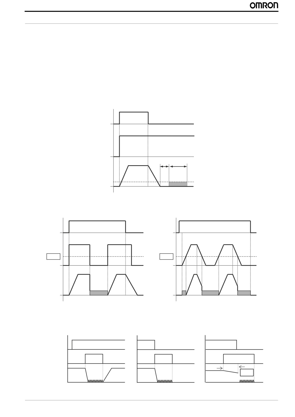
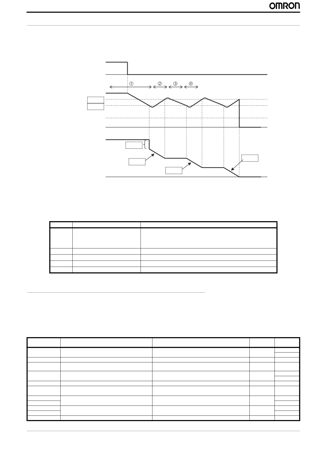
3.8 DC Braking
The DC braking feature can provide additional stopping torque during deceleration or before acceleration and is particulary use-
ful at low speeds when normal deceleration torque is minimal. This function injects a DC voltage into the motor windings which
generates a DC current that force the motor to stop.
There are several modes available depending on the application requirements:
• Normal DC braking is used when A051 is set to “01” (Enable during stop) and the RUN command (FW/RV) is turned OFF,
at the moment that deceleration stops the DC brake starts with a settable power (A054) and duration (A055). Additionally is
possible to specify a wait time between the end of the ramp and the DC braking on parameter A053, during which the motor
will free run. If free-run is selected as stopping method the DC braking will start just when the Run commands turns OFF.
DC Brake at stop
FW
ON
F-SET
A053
A055
F-OUT
DB
A054
• DC braking by frequency detection can be selected setting a051 to “02” (Frequency detection). In this case DC braking oper-
ates when the output frequency comes down to the one you specified in A052 while the RUN command is still active. Exter-
nal DB and internal DC braking are invalid during the frequency detection mode.
FW
FW
ON
ON
F-SET
F-SET
A052
A052
F-OUT
F-OUT
DB
DB
DB
DB
Eample 1: Step change in F-SET
Example 2: Analog change in F-SET
• Last option is to trigger the DC injection by a digital input when the terminal (DB) is turned ON. Set parameters A053 and
A054 to setup this function. There are several cases depending on the motor rotation and Run command status.
FW or RV DI are ON
Run from operator
Run from operator with delay
1
1
1
[FW,RV]
0
0
0
1
1
1
[DB]
0
0
0
delay
A053
F-OUT
t
t
t
MX2 Quick Start Guide Draft
21
MX2 Quick Start Guide
DC braking at startup is also possible by independent setup of parameters A057 and A058. This is useful in aplications were load
should be totally stopped before starting the movement.
Parameter
Parameter Name
Description
A051
DC braking enable
Three options; select codes:
00... Disable
01... Enable during stop
02... Frequency detection
A052
DC braking frequency
The frequency at which DC braking begins, range is from the start
frequency (B082) to 60Hz
A053
DC braking wait time
The delay from the end of controlled deceleration to start of DC
braking (motor free runs until DC braking begins), range is 0.0 to
5.0 sec.
A054
DC braking force for
Level of DC braking force, settable from 0 to 100%
deceleration
A055
DC braking time for deceleration
Sets the duration for DC braking, range is from 0.0 to 60.0 seconds
A056
DC braking / edge or level
Two options; select codes:
detection for [DB] input
00... Edge detection
01... Level detection
A057
DC braking force at start
Level of DC braking force at start, settable from 0 to 100%
A058
DC braking time at start
Sets the duration for DC braking, range is from 0.0 to 60.0 seconds
A059
Carrier frequency during
Carrier frequency of DC braking performance, range is from 2.0
DC braking
to 15.0 kHz
Be careful to avoid specifying to long braking time or to hihg carrier frequency that can cause motor overheating. If you use DC
braking is recommended to use motors with a built-in thermistor and wire it to inverter’s thermistor input.
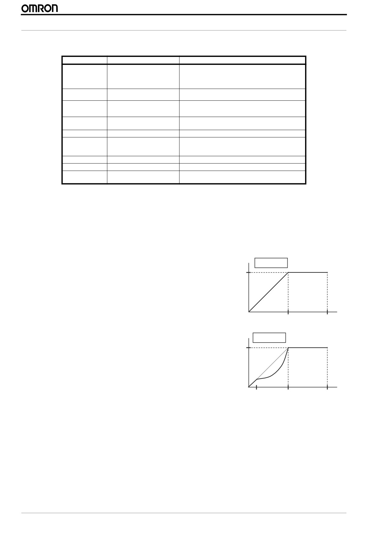
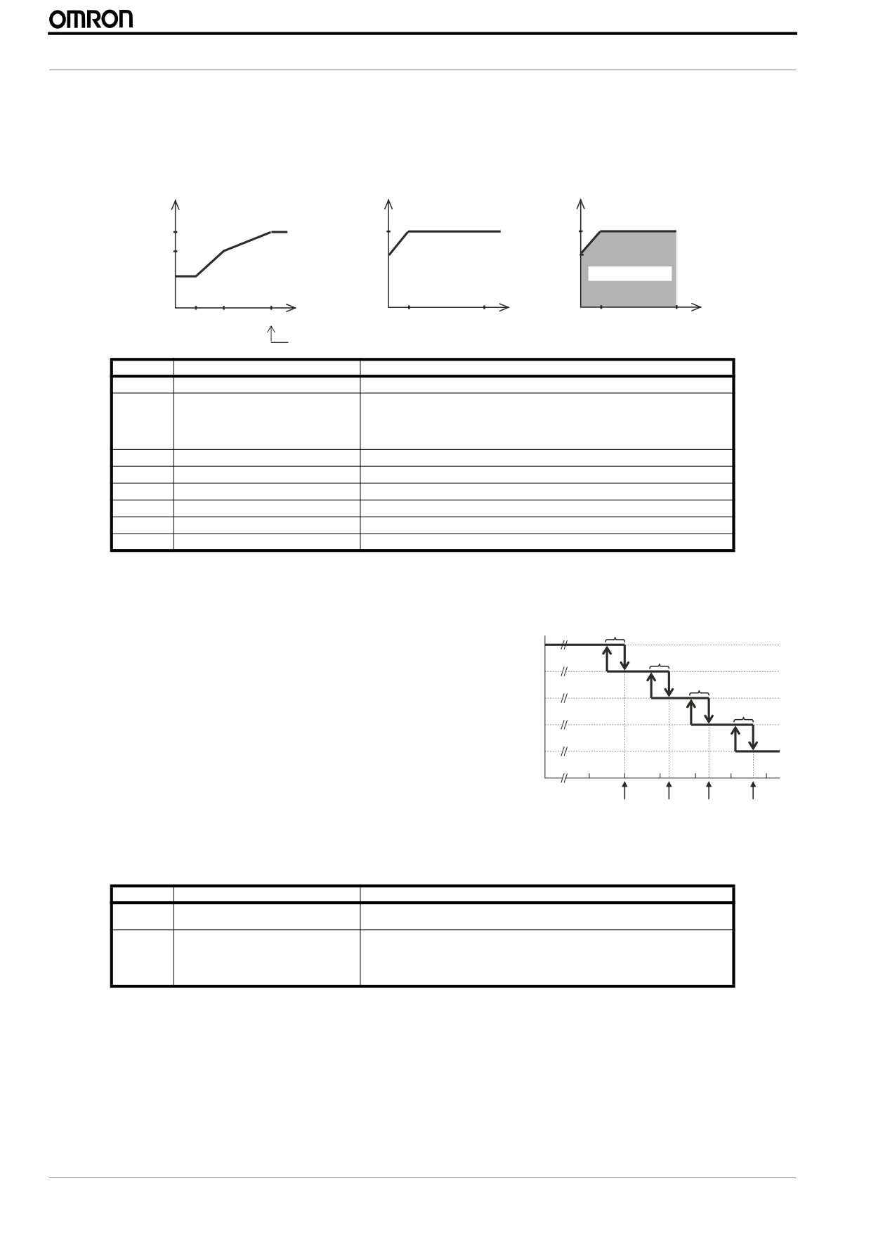
3.9 V/F Curve
The inverter generates the motor output according to the V/f algorithm selected on parameter A044. The factory default is Con-
stant torque (“00”). Review the following description to help you choose the best torque control algorithm for your application.
Review following description to help you choose the best torque control algo-
V
Constant torque
rithm for your application:.
A044 = 00
100%
• Constant and Variable (Reduced) Torque - The graph at right shows the
constant torque characteristic from 0 Hz to the base frequency A003. The
voltage remains constant for output frequencies higher than the base fre-
quency.
• Variable torque - The graph at right shows the variable (reduced) torque
Hz
curve, which has a constant torque characteristic from 0 Hz to 10% of the
0
Base
Max.
base frequency. This helps to achieve higher torque at low speed with
freq.
freq.
reduced torque curve at higher speeds.
V
A044 = 01
Variable torque
• Sensorless Vector Control - You can achieve high torque performance
(200% torque at 0.5 Hz of output frequency) without motor speed feedback
100%
but a god tuning of the motor is necessary to do it. Please remember to per-
form auto-tuning for this control method. (A044=”3”)
• Free V/F Control - The free V/F setting function allows you to set an arbi-
trary V/F characteristics by specifying the voltages and frequencies
Hz
(b100~b113) for seven points on the V/F characteristic curve (A044=”2”)
0
10% Base
Base
Max.
freq.
freq.
freq.
22
MX2 Quick Start Guide Draft
PROGRAMMING MX2
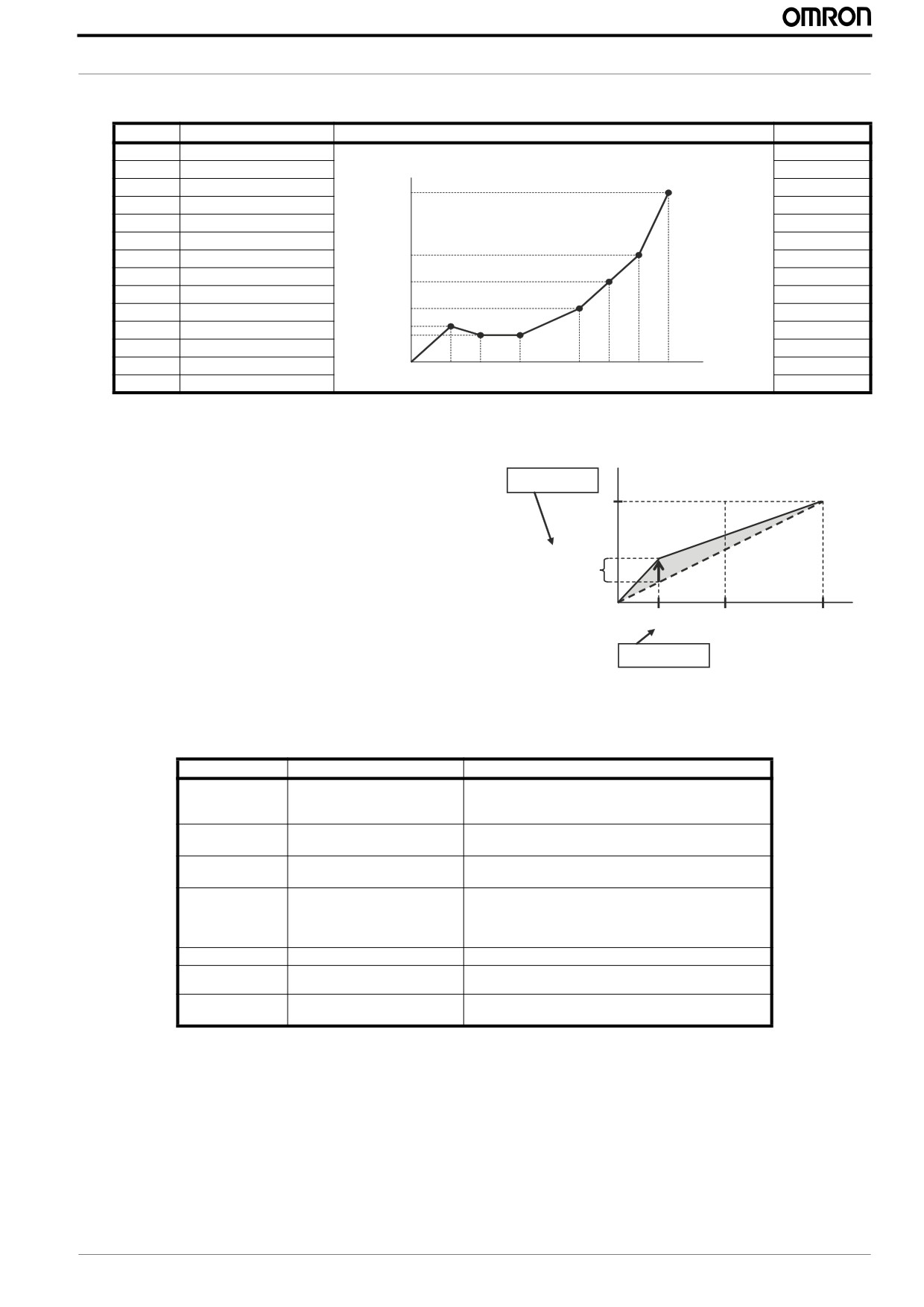
This table shows the details about the Free V/F control
Parameter
Parameter Name
Diagram
Range
b100
Free-setting V/F freq(1)
0 to b102(Hz)
b101
Free-setting V/F volt (1)
Output voltage (V)
0.0 to 800.0(V)
b102
Free-setting V/F freq(2)
b100 to b104(Hz)
b113
b103
Free-setting V/F volt (2)
0.0 to 800.0(V)
b104
Free-setting V/F freq(3)
b102 to b106(Hz)
b105
Free-setting V/F volt (3)
0.0 to 800.0(V)
b111
b106
Free-setting V/F freq(4)
b104 to b108(Hz)
b107
Free-setting V/F volt (4)
0.0 to 800.0(V)
b109
b108
Free-setting V/F freq(5)
b106 to b110(Hz)
b107
b109
Free-setting V/F volt (5)
0.0 to 800.0(V)
b101
b110
Free-setting V/F freq(6)
b108 to b112(Hz)
b103,b105
b111
Free-setting V/F volt (6)
Output freq.(Hz)
0.0 to 800.0(V)
b112
Free-setting V/F freq(7)
0 to 400.0(Hz)
0
b100 b102 b104
b106 b108
b110 b112
b113
Free-setting V/F volt (7)
0.0 to 800.0(V)
3.10 Torque boost function
Manual torque boost - Constant and Vairable torque algorithms
V
feature and asjustable torque boost curve that could help during
A042 = 5 (%)
the startup of load with very big inertia or friction. On those cases
100%
it may be necessary to increase the low frequency starting torque
characteristic by boosting the voltage above the normal V/F ratio.
A
Basically it attempsts to compensate for voltage drop in the motor
5% voltage
primary winding in the low speed range.
boost
(100%=A082)
Hz
0
Be aware that running the motor at a low speed for a long time can
1.8 Hz
30 Hz
fbase =
cause motor overheating and this is particularly true when manual
60 Hz
torque boost is activated and motor doesn’t have force ventilation.
A043 = 3 (%)
Automatic torque boost- Use the voltage compensation (A046)
and slip compensation (A047) to obtain a better performance under automatic torque boost mode (A041=01) ajusting the output
frequency and output voltage automatically depending on the load. The output voltage due automatic boost is added to the man-
ual torque boost voltage so both should be adjusted.
Parameter
Parameter Name
Description
A041
Torque boost select
Two options:
00... Manual torque boost
01... Automatic torque boost
A042
Manual torque boost value
Can boost starting torque between 0 and 20% above normal
V/f curve, range is 0.0 to 20.0%
A043
Manual torque boost frequency
Sets the frequency of the V/f breakpoint for torque boost,
range is 0.0 to 50.0%
A044
V/f characteristic curve
00... Constant torque
01... Reduced torque (1.7)
02... Free V/F
03... Sensorless vector (SLV)
A045
V/f gain
Sets voltage gain of the inverter, range is 20. to 100.%
A046
Voltage compensation gain for auto- Sets voltage compensation gain under automatic torque boost,
matic torque boost
range is 0. to 255.
A047
Slip compensation gain for auto-
Sets slip compensation gain under automatic torque boost,
matic torque boost
range is 0. to 255.
MX2 Quick Start Guide Draft
23
MX2 Quick Start Guide
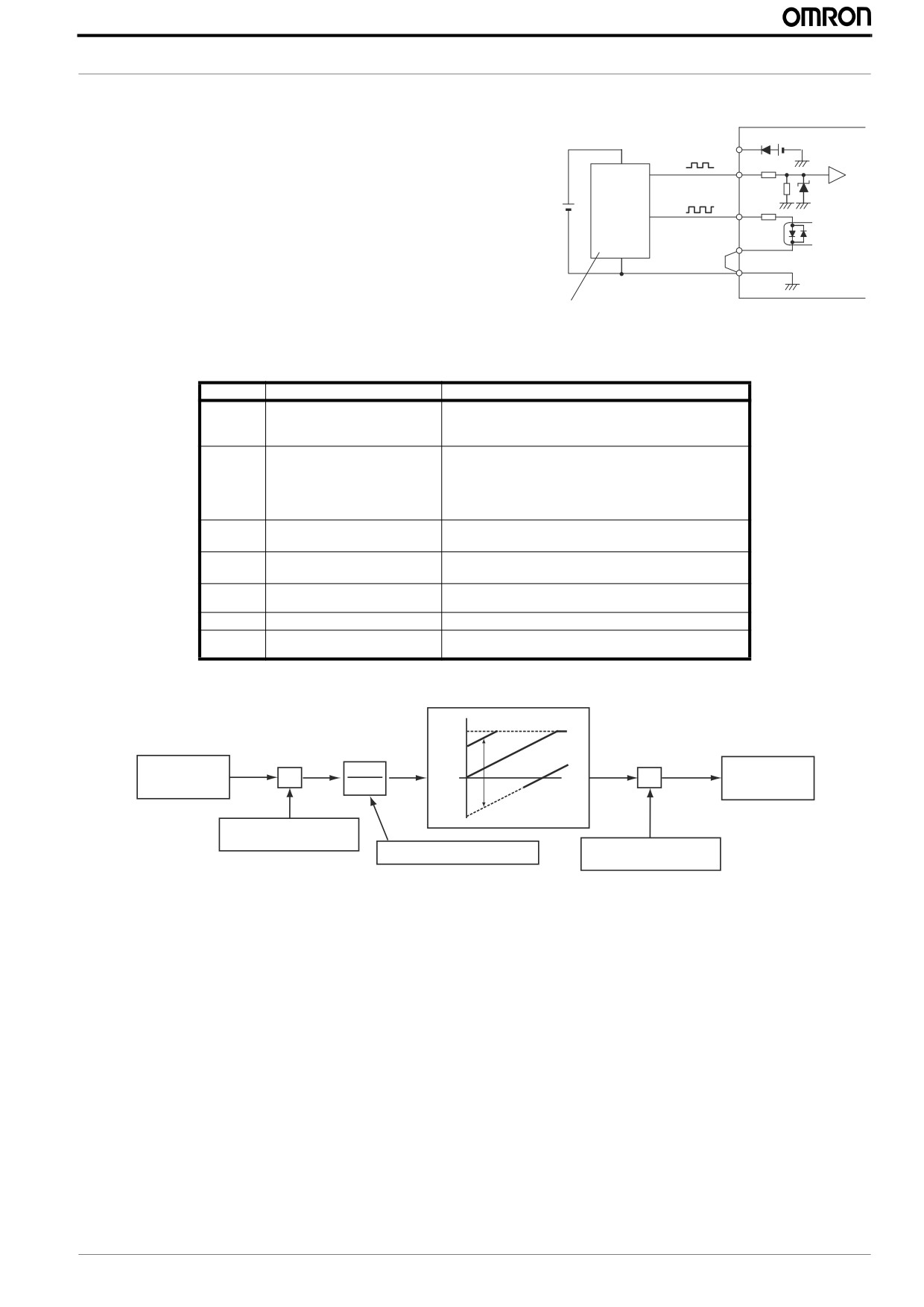
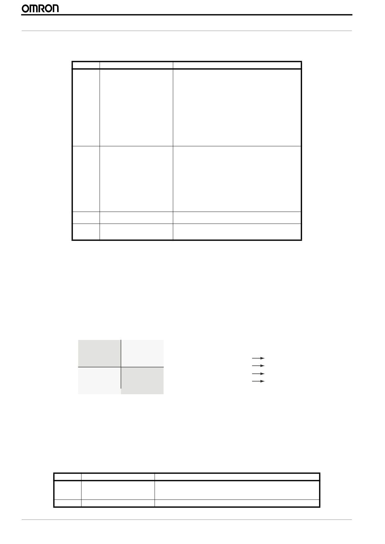
3.11 Analog inputs
MX2 provides two analog inputs, the input terminal group includes the [L], [OI],
AM H
O
OI
L
[O], and [H] terminals on the control connector, which provide for Voltage [O] or
+V Ref.
Current [OI] input. All analog input signals must use the analog ground [L].
Voltage input
If you use either the voltage or current analog input, you must select one of them
Current input
using the logic input terminal function [AT] analog type. Refer to next table for
A GND
details about the combinations between A005 and [AT] terminal. Remember that
you must also set A001=01 to select analog input as the frequency source.
V/I input select
A001
If [AT] function is not assigned to any digital input the inverter recognizes the
[AT]
Freq.
[AT] as OFF and [O]+[OI] will be used as analog input. In case either (O) or (OI)
setting
is to be referred, please ground the other.
A005
[AT] Input
Analog Input Configuration
AM H
O
OI
L
00
ON
[O]
OFF
[OI]
4-20 mA
02
ON
[O]
OFF
Integrated POT on external panel
0-10 V
03
ON
[OI]
1 to 2kΩ, 2 W
OFF
Integrated POT on external panel
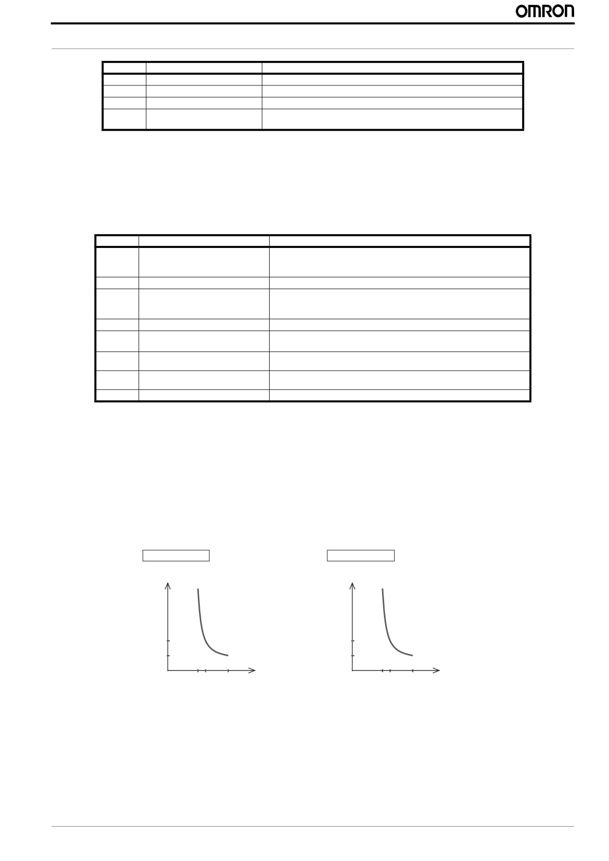
For [O] input and using parameters A013 and A014 you could select the portion of
Max frequency
the voltage input range. Parameters A011 and A012 select the start and end fre-
quency of the converted output frequency range, respectively. When the line does
A012
A102
not begin at the origin (A011 and A013 > 0), then A015 defines whether the
A015=00
inverter outputs 0 Hz or the A011 specified frequency for analog input below A013.
A105=00
Parameter
Parameter name
Description
A015=01
A011
[O] start frequency
0.00 to 400.00
A105=01
A011
A012
[O] end frequency
0.00 to 400.00
A101
%
A013
[O] start voltage
0. to 100%
0
A014
[O] end voltage
0. to 100%
0%
A013
A014
100%
A015
[O] start frequency enable
00... Use offset (A011 value)
0V
A103
A104
10V
01..
Use 0Hz
Input scale
A101
[OI] start frequency
0.00 to 400.00
A102
[OI] end frequency
0.00 to 400.00
A103
[OI] start voltage
0. to 100%
A104
[OI] end voltage
0. to 100%
A105
[OI] start frequency enable
00... Use offset (A101 value)
01..
Use 0Hz
A016
Analog input filter
Range n = 1 to 31,
1 to 30 : ×2ms filter
31: 500ms fixed filter with ±0.1kHz hys.
24
MX2 Quick Start Guide Draft
PROGRAMMING MX2
3.12 Digital inputs
The function codes in the following table let you assign between a wide range of functions to any of the seven logic inputs for the
MX2 inverter. The functions C001 through C007 configure the terminals [1] through [7] respectively. The "value" of these partic-
ular parameters is not a scalar value, but it is a discrete number that selects one option from many available options.
Input Function Summary Table
Option
Terminal
Function Name
Description
Code
Symbol
00
FW
FORWARD Run/Stop
ON
Inverter is in Run Mode, motor runs forward
OFF
Inverter is in Stop Mode, motor stops
01
RV
Reverse Run/Stop
ON
Inverter is in Run Mode, motor runs reverse
OFF
Inverter is in Stop Mode, motor stops
02
CF1
Multi-speed Select, Bit 0 (LSB)
ON
Binary encoded speed selection bit 3 to bit 0
03
CF2
Multi-speed Select, Bit 1
04
CF3
Multi-speed Select, Bit 2
OFF
05
CF4
Multi-speed Select, Bit 3 (MSB)
06
JG
Jogging
ON
Inverter is in Run Mode, output to motor runs at jog parameter frequency
07
DB
External DC braking
ON
DC braking will be applied during deceleration
08
SET
Set (select) 2nd motor Data
ON
The inverter uses 2nd motor parameters for generating frequency output to motor
OFF
The inverter uses 1st (main) motor parameters for generating frequency output to motor
09
2CH
2-stage Acceleration and Decel-
ON
Frequency output uses 2nd-stage acceleration and deceleration values
eration
OFF
Frequency output uses standard acceleration and deceleration values
11
FRS
Free-run Stop
ON
Causes output to turn OFF, allowing motor to free run (coast) to stop
12
EXT
External Trip
ON
When assigned input transitions OFF to ON, inverter latches trip event and displays E 12
OFF
No trip event for ON to OFF, any recorded trip events remain in history until reset
13
USP
Unattended Start Protection
ON
On powerup, the inverter will not resume a Run command
OFF
On powerup, the inverter will resume a Run command that was active before power loss
14
CS
Commercial power source swi-
ON
Motor can be driven by commercial power
tchover
OFF
Motor is driven via the inverter
15
SFT
Software Lock
ON
The keypad and remote programming devices are prevented from changing parameters
OFF
The parameters may be edited and stored
16
AT
Analog Input Voltage/Current
ON
Refer to Analog In put selection
Select
OFF
18
RS
Reset Inverter
ON
The trip condition is reset, the motor output is turned OFF, and powerup reset is asserted
OFF
Normal power-ON operation
19
PTC
PTC thermistor Thermal
ANLG
When a thermistor is connected to terminal [5] and [L], the inverter checks for over-tem-
Protection (C005 only)
perature and will cause trip event and turn OFF output to motor
OPEN
A disconnect of the thermistor causes a trip event, and the inverter turns OFF the motor
20
STA
Start (3-wire interface)
ON
Starts the motor rotation
21
STP
Stop (3-wire interface)
ON
Stops the motor rotation
22
F/R
FWD, REV
ON
Selects the direction of motor rotation: ON = FWD. While the motor is rotating, a change
(3-wire interface)
of F/R will start a deceleration, followed by a change in direction
OFF
Selects the direction of motor rotation: OFF = REV. While the motor is rotating, a change
of F/R will start a deceleration, followed by a change in direction
23
PID
PID Disable
ON
Temporarily disables PID loop control. Inverter output turns OFF as long as PID Enable is
active (A071=01)
OFF
Has no effect on PID loop operation, operates normally if PID Enable is active (A071=01)
24
PIDC
PID Reset
ON
Resets the PID loop controller. Main consequence is that integrator sum is forced to zero
27
UP
Remote Control UP Function
ON
Accelerates (increases output frequency) motor from current frequency
(motorized speed pot.)
28
DWN
Remote Control Down Function
ON
Decelerates (decreases output frequency) motor from current frequency
(motorized speed pot.)
29
UDC
Remote Control Data Clearing
ON
Clears the UP/DWN frequency memory by forcing it to equal the set frequency parameter
F001. Setting C101 must be set=00 to enable this function to work
31
OPE
Operator Control
ON
Forces the source of the output frequency setting A001 and the source of the Run com-
mand A002 to be from the digital operator
OFF
Source of output frequency set by A001 and source of Run command set by A002 is used
32
SF1
Multi-speed Select, Bit 1
ON
Bit encoded speed select, Bit 1 to Bit 7
33
SF2
Multi-speed Select, Bit 2
34
SF3
Multi-speed Select, Bit 3
35
SF4
Multi-speed Select, Bit 4
OFF
36
SF5
Multi-speed Select, Bit 5
37
SF6
Multi-speed Select, Bit 6
38
SF7
Multi-speed Select, Bit 7
39
OLR
Overload Restriction Source
ON
Perform overload restriction
Changeover
OFF
Normal operation
MX2 Quick Start Guide Draft
25
MX2 Quick Start Guide
Input Function Summary Table
Option
Terminal
Function Name
Description
Code
Symbol
40
TL
Torque Limit Selection
ON
Setting of b040 is enabled
OFF
Max. torque is limited with 200%
41
TRQ1
Torque limit switch 1
ON
Torque limit related parameters of Powering/regen, and FW/RV modes are selected by the
combinations of these inputs.
42
TRQ2
Torque limit switch 2
OFF
44
BOK
Brake confirmation
ON
Brake confirmation signal received
OFF
Brake confirmation signal not received
46
LAC
LAD cancellation
ON
Set ramp times are ignored. Inverter output immediately follows the freq. command.
OFF
Accel. and/or decel. is according to the set ramp time
47
PCLR
Pulse counter clear
ON
Clear the position deviation data
OFF
Maintain the position deviation data
50
ADD
ADD frequency enable
ON
Adds the A145 (add frequency) value to the output frequency
OFF
Does not add the A145 value to the output frequency
51
F-TM
Force Terminal Mode
ON
Force inverter to use input terminals for output frequency and Run command sources
OFF
Source of output frequency set by A001 and source of Run command set by A002 is used
52
ATR
Enable torque command input
ON
Torque control command input is enabled
OFF
Torque control command input is disabled
53
KHC
Clear watt-hour data
ON
Clear watt-hour data
56
MI1
General purpose input (1)
ON
General purpose input (1) to (7) under Drive programming
57
MI2
General purpose input (2)
58
MI3
General purpose input (3)
59
MI4
General purpose input (4)
OFF
60
MI5
General purpose input (5)
61
MI6
General purpose input (6)
62
MI7
General purpose input (7)
65
AHD
Analog command hold
ON
Analog command is held
OFF
Analog command is not held
66
CP1
Multistage-position switch (1)
ON
Multistage position commands are set according to the combination of these switches.
67
CP2
Multistage-position switch (2)
OFF
68
CP3
Multistage-position switch (3)
69
ORL
Limit signal of homing
ON
Limit signal of homing is ON
70
ORG
Trigger signal of homing
ON
Starts homing operation
73
SPD
Speed/position changeover
ON
Speed control mode
OFF
Position control mode
77
GS1 *
GS1 input
ON
EN60204-1 related signals: Signal input of "Safe torque off" function.
78
GS2 *
GS2 input
OFF
81
485
Start EzCOM
ON
Starts EzCOM
OFF
No execution
82
PRG
Executing Drive programming
ON
Executing Drive program
OFF
No execution
83
HLD
Retain output frequency
ON
Retain the current output frequency
84
ROK
Permission of Run command
ON
Run command permitted
85
EB
Rotation direction detection
ON
Forward rotation
(C007 only)
OFF
Reverse rotation
86
DISP
Display limitation
ON
Only a parameter configured in b038 is shown
OFF
All the monitors can be shown
255
no
No function
ON
(input ignored)
All this functions could be assigned to any of the multi-function inputs on parameters C001 to C007, select if the input will be
normally open or normally close and the response time of the input.
Parameter
Parameter name
Description
C001
Input [1] function
Select input terminal [1] function
C002
Input [2] function
Select input terminal [2] function
C003
Input [3] function
Select input terminal [3] function
[GS1 assignable]
C004
Input [4] function
Select input terminal [4] function
[GS2 assignable]
C005
Input [5] function
Select input terminal [5] function
[PTC assignable]
C006
Input [6] function
Select input terminal [6] function
C007
Input [7] function
Select input terminal [7] function
26
MX2 Quick Start Guide Draft
PROGRAMMING MX2
Parameter
Parameter name
Description
C011
Input [1] active state
Select logic conversion, two option codes:
C012
Input [2] active state
00... normally open [NO]
01... normally closed [NC]
C013
Input [3] active state
C014
Input [4] active state
C015
Input [5] active state
C016
Input [6] active state
C017
Input [7] active state
C160
Input [1] response time
Sets response time of each input terminal,
set range:
C161
Input [2] response time
0 (x 2 [ms]) to 200 (x 2 [ms])
C162
Input [3] response time
C163
Input [4] response time
C164
Input [5] response time
C165
Input [6] response time
C166
Input [7] response time
d005
Intelligent input
ON
terminal status
OFF
7
6
5
4
3
2
1
Terminal numbers
An input terminal configured for option code 18 ([RS] Reset command) cannot be configured for normally closed operation.
3.13 Digital outputs
Function codes in the following table let you assign different options into logical outputs (terminals [11],[12] and [AL]) on
parameter C021, C022 and C026..
Input Function Summary Table
Option
Terminal
Function Name
Description
Code
Symbol
00
RUN
Run Signal
ON
When the inverter is in Run Mode
01
FA1
Frequency Arrival Type 1-
ON
When output to motor is at the set frequency
Constant Speed
OFF
When output to motor is OFF, or in any acceleration or deceleration ramp
02
FA2
Frequency Arrival Type 2-
ON
When output to motor is at or above the set freq., even if in accel (C042) or
Over frequency
decel (C043) ramps
OFF
When output to motor is OFF, or at a level below the set frequency
03
OL
Overload Advance Notice
ON
When output current is more than the set threshold (C041) for the overload sig-
Signal 1
nal
04
OD
Output Deviation for PID
ON
When PID error is more than the set threshold for the deviation signal
Control
05
AL
Alarm Signal
ON
When an alarm signal has occurred and has not been cleared
06
FA3
Frequency Arrival Type 3-
ON
When output to motor is at the set frequency, during accel (C042) and decel
Set frequency
(C043).
07
OTQ
Over/under Torque Signal
ON
Estimated motor torque exceeds the specified level
09
UV
Undervoltage
ON
Inverter is in Undervoltage
10
TRQ
Torque Limited Signal
ON
Torque limit function is executing
11
RNT
Run Time Expired
ON
Total running time of the inverter exceeds the specified value
12
ONT
Power ON time Expired
ON
Total power ON time of the inverter exceeds the specified value
13
THM
Thermal Warning
ON
Accumulated thermal count exceeds the C061 set value
19
BRK
Brake Release Signal
ON
Output for brake release
20
BER
Brake Error Signal
ON
Brake error has occurred
21
ZS
Zero Hz Speed Signal
ON
Output frequency falls below the threshold specified in C063
22
DSE
Speed Deviation Excessive
ON
Deviation of speed command and actual speed exceeds the specified value
P027.
23
POK
Positioning Completion
ON
Positioning is completed
24
FA4
Frequency Arrival Type 4-
ON
When output to motor is at or above the set freq., even if in accel (C045) or
Over frequency
decel (C046) ramps
25
FA5
Frequency Arrival Type 5-
ON
When output to motor is at the set frequency, during accel (C045) and decel
Set frequency
(C046).
26
OL2
Overload Advance Notice
ON
When output current is more than the set threshold (C111) for the overload sig-
Signal 2
nal
27
ODc
Analog Voltage Input Dis-
ON
When the [O] input value < B070 setting (signal loss detected)
connect Detection
28
OIDc
Analog Current input Dis-
ON
When the [OI] input value < B071 setting (signal loss detected)
connect Detection
MX2 Quick Start Guide Draft
27
MX2 Quick Start Guide
Input Function Summary Table
Option
Terminal
Function Name
Description
Code
Symbol
31
FBV
PID Second Stage Output
ON
Transitions to ON when the inverter is in RUN Mode and the PID Process Vari-
able (PV) is less than the Feedback Low Limit (C053)
OFF
Transitions to OFF when the PID Process Variable (PV) exceeds the PID High
Limit (C052), and transitions to OFF when the inverter goes from Run Mode to
Stop Mode
32
NDc
Network Disconnect Detect
ON
When communications watchdog timer (period specified by C077) has time out
33
LOG1
Logic Output Function 1
ON
When the Boolean operation specified by C143 has a logical "1" result
34
LOG2
Logic Output Function 2
ON
When the Boolean operation specified by C146 has a logical "1" result
35
LOG3
Logic Output Function 3
ON
When the Boolean operation specified by C149 has a logical "1" result
39
WAC
Capacitor Life Warning Sig-
ON
Lifetime of internal capacitor has expired.
nal
40
WAF
Cooling Fan Warning Signal
ON
Lifetime of cooling fan has expired.
41
FR
Starting Contact Signal
ON
Either FW or RV command is given to the inverter
OFF
No FW or RV command is given to the inverter, or both are given to the inverter
42
OHF
Heat Sink Overheat Warning
ON
Temperature of the heat sink exceeds a specified value (C064)
43
LOC
Low load detection
ON
Motor current is less than the specified value (C039)
44
MO1
General Output 1
ON
General output 1 is ON (Used by Drive programing)
45
MO2
General Output 2
ON
General output 2 is ON (Used by Drive programing)
46
MO3
General Output 3
ON
General output 3 is ON (Used by Drive programing)
50
IRDY
Inverter Ready Signal
ON
Inverter can receive a run command
51
FWR
Forward Rotation
ON
Inverter is driving the motor in forward direction
52
RVR
Reverse Rotation
ON
Inverter is driving the motor in reverse direction
53
MJA
Major Failure Signal
ON
Inverter is tripping with major failure
54
WCO
Window Comparator for
ON
Analog voltage input value is inside of the window comparator
Analog Voltage Input
55
WCOI
Window Comparator for
ON
Analog current input value is inside of the window comparator
Analog Current Input
58
FREF
Frequency Command
ON
Frequency command is given from the operator
Source
59
REF
Run Command Source
ON
Run command is given from the operator
60
SETM
2nd motor Selection
ON
2nd motor is being selected
62
EDM
STO (Safe Torque Off) Per-
ON
STO is being performed
formance Monitor
(Output terminal 11 only)
63
OPO
Option card output
ON
(output terminal for option card)
255
no
Not used
ON
-
In the same way of that the digital inputs is possible to choose between normally close and normally open and even is possible to
use some On and Off delay for each of the outputs.
Parameter
Parameter name
Description
Output [11] function
C021
Programmable functions available for logic
[EDM assignable]
(discrete) outputs transistor type
C022
Output [12] function
Programmable functions available for logic
C026
Alarm relay function
(discrete) outputs relay type
C031
Output [11] active state
Select logic conversion, two option codes:
C032
Output [12] active state
00... normally open [NO]
C036
Alarm relay active state
01... normally closed [NC]
C130
Output [11] on delay
Set range is 0.0 to 100.0 sec.
C131
Output [11] off delay
C132
Output [12] on delay
Set range is 0.0 to 100.0 sec.
C133
Output [12] off delay
C140
Relay output on delay
Set range is 0.0 to 100.0 sec.
C141
Relay output off delay
C132
Output [12] on delay
Set range is 0.0 to 100.0 sec.
C133
Output [12] off delay
ON
Intelligent output
d006
OFF
terminal status
Relay
12 11
28
MX2 Quick Start Guide Draft
PROGRAMMING MX2
3.14 Pulse input
Pulse train input in terminal EA could be used as frequency refer-
Vcc
P24
MX2
ence, PID input, encoder feedback for position control and also as
an input for Drive Programming. The maximum frequency for this
A
EA
pulse input is 32KHz and the selection is done by parameter P003.
Encoder
7/EB
Encoder feedback setting is set in parameter P004, but please
B
remember that this is just for positioning function and close loop
PLC
vector control can’t be performed with MX2 because this encoder
L
reading is not included into the speed loop. For selection “01” and
“02” on P004 is possible to use a 2-phase differential encoder but
GND
the second channel should be connect to multi-funciton input 7
PNP open collector type or
voltage output type encoder
with the function code “EB”.
Parameter
Parameter name
Description
P003
[EA] terminal selection
00… Speed reference (incl. PID)
01… For control with encoder feedback
02… Extended terminal for EzSQ
P004
Pulse train input mode selection for
Four option codes:
feedback
00…Single-phase pulse [EA]
01…2-phase pulse (90° difference) 1 ([EA] and [EB])
02…2-phase pulse (90° difference) 2 ([EA] and [EB])
03…Single-phase pulse [EA] and direction signal [EB]
P011
Encoder pulse setting
Sets the pulse number (ppr) of the encoder,
set range is 32~1024 pulses
P055
Pulse train input frequency scale set-
Sets the pulse numbers at max. frequency,
ting
set range is 1.0~32.0 kHz
P056
Pulse train input frequency filter
Set range is 0.01~2.00 sec.
time constant setting
P057
Pulse train input bias setting
Set range is -100~100 %
P058
Limitation of the pulse train input
Set range is 0~100 %
setting
The pulse input when used as frequency reference could be adjusted with parameters P055 to P058 according to this diagram
Limit
(P058)
Frequency
1
Bias(P057)
Frequency
/
X
measurement
1 + sT
Reference
Frequency Scale (P055)
(1.0 to 32 kHz)
Maximum Frequency
Primary Delay Filter (P056)
(A004)
MX2 Quick Start Guide Draft
29
MX2 Quick Start Guide
3.15 Analogue and pulse outputs
Several monitors are available through the pulse output [EO] or the analogue output [AM].
Parameter
Parameter name
Description
C027
[EO] terminal selection (Pulse/PWM
00... Output frequency (PWM)
output)
01... Output current (PWM)
02... Output torque (PWM)
03... Output frequency (Pulse train)
04... Output voltage (PWM)
05... Input power (PWM)
06... Electronic thermal load ratio (PWM)
07... LAD frequency (PWM)
08... Output current (Pulse train)
10... Heat sink temperature (PWM)
12... General output (PWM)
15... Pulse train input monitor
16... Option(PWM)
C028
[AM] terminal selection (Analog
00... Output frequency
voltage output 0...10V)
01... Output current
02... Output torque
04... Output voltage
05... Input power
06... Electronic thermal load ratio
07... LAD frequency
10... Heat sink temperature
11... Output torque (with code)
13... General output
16... Option
C030
Digital current monitor reference
Current with digital current monitor output at 1,440Hz Range is
value
20%~200% of rated current
C047
Pulse train input/output scale con-
If EO terminal is configured as pulse train input (C027=15), scale
version
conversion is set in C047. Pulse-out = Pulse-in (C047) Set range is
0.01 to 99.99
For the pulse train output there are two types of outputs, code “03”, “08” and “15” outputs a pulse train with a 50% duty cycle
while the PWM has a fixed frequency of 156.25Hz were the duty cycle is changed depending on the output.
3.16 Torque limit
Torque limit function allows you to limit the motor output when sensorless vector control (SLV) is selected in A044. This func-
tion has limited accuracy and repeatability and is realiable only above 15 - 20Hz. You can choose between models using parame-
ter b040.
Quadrant specific setting mode (b040=00) in which individual torque limit value are applied on the four quadrants (forward
powering, reverse regeneration..) by torque limits 1 to 4 (b041 to b044)
Torque
(+)
Digital inputs
Torque limit
Regeneration
Powering
TRQ2 TRQ1
selection
(b042)
(b041)
OFF OFF
b041
Reverse rotation
Forward rotation
OFF ON
b042
Powering
Regeneration
ON OFF
b043
(b043)
(b044)
ON ON
b044
Torque
(-)
Terminal-switching mode (b040=01) where the torque limit values set in torque limits 1 to 4 (b041 to b044) are switched
depending on the combination of the states of the torque limit switch terminals 1 and 2 (TRQ1 and TRQ2) assigned to digital
inputs.
Analog voltage input mode (b040=02) where the torque limit value is set by a voltage applied to the terminal O. Range 0 to
10V corresponds with torque limit range between 0 and 200% that is valid for all operating states.
If “TL” torque limit enable functions has been assigned to any of the multi-function inputs the setting of parameter b040 only is
valid when this input is ON. No torque limitation will be applied whe the input is OFF.
Parameter
Parameter name
Description
b040
Torque limit selection
00
Quadrant-specific setting mode
01
Terminal-switching mode
02
Analog voltage input mode(O)
b041
Torque limit 1 (fwd/power)
Torque limit level in forward powering quadrant, range is 0 to 200% / no(disabled)
30
MX2 Quick Start Guide Draft
PROGRAMMING MX2
Parameter
Parameter name
Description
b022
Torque limit 2 (rev/regen.)
Torque limit level in reverse regen. quadrant, range is 0 to 200% / no(disabled)
b043
Torque limit 3 (rev/power)
Torque limit level in reverse powering quadrant, range is 0 to 200% / no(disabled)
b044
Torque limit 4 (fwd/regen.)
Torque limit level in forward regen. quadrant, range is 0 to 200% / no(disabled)
b045
Torque LAD STOP selection
00
Disable
01
Enable
100% torque is referred to inverter rated current, absolute torque value is up the motor to be combined.
3.17 Torque control
Torque control in open loop could be achieve with following parameters. 100% torque is referred to inverter rated current but
absolute torque value depends on the motor connected. It has limited accuracy and working range so is recomended only above
15 - 20Hz and over 20 - 30% of the motor torque capacity.
Parameter
Parameter name
Description
P033
Torque command input selection
00… Analog voltage input [O]
01… Analog current input [OI]
03… Operator, 06…Option
P034
Torque command level input
Set range is 0~200%
P036
Torque bias mode selection
00… According to the sign
01… According to the rotation direction
05… Option
P037
Torque bias value setting
Range is -200~200%
P038
Torque bias polar selection
00… No bias
01… Operator
P039
Speed limit of Torque control (Forward
Set range is 0.00~120.00Hz
rotation)
P040
Speed limit of Torque control (Reverse
Set range is 0.00~120.00Hz
rotation)
P041
Speed / Torque control switching time
Set range is 0 to 1000 ms
To enable the torque control is necessary to assign the “ATR” (Enable torque command input) to one of the multi-function inputs
and set it to ON. When the input is OFF the inverter will work in speed mode.
At low speed, small torque command or 4 quadrant control applications the perfomance of this function will be limited due the
open loop system.
3.18 Electronic thermal overload
The thermal overload detection protects the inverter and motor from overheating due to an excessive load using a current
inverse time curve to determine the trip point. The characteristic curve depends on dual rate setting in b049 and is unique for
both inverter and motor but reduction rate depending on the frequency could be selected in parameter b013.
b049=00 (HD )
b049=01 (ND )
Trip time (s)
Trip time (s)
60
60
3.0
0.5
Percentage of
Percentage of
0
109%
150%
200%
0
116%
120%
150%
b012/b212
b012/b212
MX2 Quick Start Guide Draft
31
MX2 Quick Start Guide
b013 could be used to match the torque characteristic with the load. Output current on the winding is used for this calculation as
is proportional to the torque generated by the motor. That’s why the current level has to be set in parameter b012 with a range
that goes from 20 to 100% of the inverter rated current.
Reduced Torque (b013=00)
Constant Torque (b013=01)
Free setting (b013=02)
Reduction rate
Reduction rate
Reduction rate
b012 x 1.0
b012 x 1.0
b012 x 1.0
b012 x 0.8
b012 x 0.8
b012 x 0.8
b020
Setting range
b018
b012 x 0.6
b016
0
5
16
50
0
3
60
0
b015
b017
b019
Output frequency [Hz]
Base FQ
Output frequency [Hz]
Output frequency [Hz]
Parameter
Parameter name
Description
b012
Level of electronic thermal
Set a level between 20% and 100% for the rated inverter current.
b013
Electronic thermal characteristic
Select from three curves, option codes:
00... Reduced torque
01... Constant torque
02... Free setting
b015
Free setting electronic thermal ~freq.1
Range is 0 to 400 Hz
b016
Free setting electronic thermal ~current1
Range is 0 to inverter rated current Amps
b017
Free setting electronic thermal ~freq.2
Range is 0 to 400 Hz
b018
Free setting electronic thermal ~current2
Range is 0 to inverter rated current Amps
b019
Free setting electronic thermal ~freq.3
Range is 0 to 400 Hz
b020
Free setting electronic thermal ~current3
Range is 0 to inverter rated current Amps
3.19 Carrier frequency (PWM)
The internal switching frequency of the inverter circuitry (also called chop-
Carrier freq.
5%
per frequency) defines the IGBT communtation speed that is used to gen-
15kHz
erated the output frequency. Is adjustable from 2.0 to 15KHz (depending
5%
12kHz
on the inverter size) where the audible noise decrease at higher frequencies
5%
while the RFI noise and leakage current increase.
9kHz
5%
6kHz
The carrier frequency is adjusted by parameter b083 but the activation of
the aumatic carrier frequency reduction on parameter b089 could reduce
3kHz
the selected value when the output current increase or when the heat sink
temperature is too high. On this way is possible to have a high carrier fre-
0
50
100
quency with light loads and avoid the derating when the load increase. The
60%
72%
84%
96%
upper limit is defined by b083 while the lower one is 3KHz with 2KHz per
Output current
second reduction rate.
Parameter
Parameter name
Description
b083
Carrier frequency
Sets the PWM carrier (internal switching frequency), range is
2.0 to 15.0 kHz
b089
Automatic carrier frequency reduction
Three option codes:
00
Disabled
01
Enabled, depending on the output current
02
Enabled, depending on the heat-sink temperature
32
MX2 Quick Start Guide Draft
PROGRAMMING MX2
3.20 PID Function
When enabled, the built-in PID loop calculates an ideal inverter output value that cause the loop feedback process variable (PV)
to move closer to the set point value (SP). The frequency command is used as SP and the PID loop algorithm will read the analog
input for the process variable and calculate the proper inverter output to reach it.
Setpoint
PID
Freq.
External
+ Error
Inverter
Motor
SP
Calculation
Process
PV
Process Variable (PV)
Sensor
In standard operation, inverter uses a reference source selected by A001 for the output frequency which may be a fixed or vari-
able value. To enable PID operation is necessary to set A071 to “01” and this will cause the inverter to calculate the target fre-
quiency or set point. This presents some advantges like potential energy saving and direct control over the process variable
instead of the motor speed.
Parameter
Parameter name
Description
A071
PID enable
00... PID Disable
01... PID Enable
02... PID Enable with reverse output
A072
PID proportional gain
Proportional gain has a range of 0.00 to 25.00
A073
PID integral time constant
Integral time constant has a range of 0.0 to 3600 seconds
A074
PID derivative time constant
Derivative time constant has a range of 0.0 to 100 seconds
A075
PV scale conversion
Process Variable (PV), scale factor (multiplier), range of 0.01 to 99.99
A076
PV source
Selects source of Process Variable (PV), option codes:
00..
[OI] terminal (current in)
01..
[O] terminal (voltage in)
02 ..
ModBus network
03..
Pulse train input 10 Calculate function output
A077
Reverse PID action
Two option codes: 00 PID input = SP-PV 01 PID input = -(SP-PV)
A078
PID output limit
Sets the limit of PID output as percent of full scale, range is 0.0 to 100.0%
A079
PID feed forward selection
00... Disabled
01...
[O] terminal (voltage in)
02...
[OI] terminal (current in)
A156
PID sleep function action threshold
Sets the threshold for the action, set range 0.0~400.0 Hz
A157
PID sleep function action delay time
Sets the delay time for the action, set range 0.0~25.5 sec
A071
PID enable
00... PID Disable
01... PID Enable
02... PID Enable with reverse output
3.21 Current limitation functions
Overload Restriction reduce the output frequency while motoring or increase
Motor
it during regeneration to restrict the overload when the output current exceeds
current
Restriction area
a certain limit. You can adjust the inverter to apply overload retriction only
B022
during constant speed allowing higher currents for acceleration.
Additionally two separate set of parameters are avaiable and is possible to
0
t
choose between them by intelligent input terminal “39: OLR”.
Regenerating
Output
B023
frequency
Powering
t
0
B023
MX2 Quick Start Guide Draft
33
MX2 Quick Start Guide
Over-current Trip Suppression function monitors the motor current
B027 = 01
OC LAD STOP = Enabled
and actively changes the output frequency profile to keep the motor cur-
Motor
Approx. 150% of the inverter
rent below 150% of the motor rated current. Basically the acceleration
current
rated current
ramp is at stopped above this current and it only restarts when the cur-
rent goes below again. It avoids the trip but the total acceleration time
could be longer when this function is enable.
0
t
Additionally should be considered that this function doesn’t operate
keeping a constant motor current so is still possible to have an over-cur-
Output
Stops accel
frequency
rent trip during extreme acceleration.
Resumes accel
0
t
Set acc time
Actual acc time
Parameter
Parameter name
Description
b021
Overload restriction operation mode
00
Disabled
01
Enabled for acceleration and constant speed
02
Enabled for constant speed only
03
Enabled for acceleration and constant speed, increase speed at regen.
b022
Overload restriction level
Sets the level of overload restriction, between 20% and 200% of the rated current of
the inverter, setting resolution is 1% of rated current
b023
Deceleration rate at overload restriction
Sets the deceleration rate when inverter detects overload, range is 0.1 to 3000.0, reso-
lution 0.1
b024
Overload restriction operation mode 2
00
Disabled
01
Enabled for acceleration and constant speed
02
Enabled for constant speed only
03
Enabled for acceleration and constant speed, increase speed at regen.
b025
Overload restriction level 2
Sets the level of overload restriction, between 20% and 200% of the rated current of
the inverter, setting resolution is 1% of rated current
b026
Deceleration rate 2 at overload restriction
Sets the deceleration rate when inverter detects overload, range is 0.1 to 3000.0, reso-
lution 0.1
b027
OC suppression selection *
00
Disabled
01
Enabled
3.22 Overvoltage protection
DC Bus AVR (Automatic Voltage regulation) helps to avoid an overvoltage
b130 = 01
trip when the DC bus voltage increase due regeneration during decelera-
DC bus voltage
tion. The function keeps the DC bus voltage stable at certain level regulating
the deceleration ramp by a PI function. Please note that the actual decelera-
Threshold voltage to start DC bus AVR (B131)
tion time can be longer in this case.
Parameter
Parameter name
Description
b130
Deceleration overvoltage sup-
00
Disabled
t
pression enable
01
Enabled
02
Enabled with accel.
Freq
b131
Decel. overvolt. suppress level
DC bus voltage of suppression. Range is:
200 V class 330 to 395
400 V class 660 to 790
b132
Decel. overvolt. suppress const.
Accel. rate when b130=02.
Set range: 0.10 ~ 30.00 sec.
t
b133
Decel. overvolt. suppress
Proportional gain when b130=01. Range is:
proportional gain
0.00 to 5.00
Normal
DC bus AVR
b134
Decel. overvolt. suppress
Integration time when b130=01. Range is: 0.00
operation
integral time
to 150.0
34
MX2 Quick Start Guide Draft
PARAMETER LIST
3.23 Controlled stop at power loss
This function is intended to achieve a controlled stop and avoid free-running of the motor when power is lost during run mode.
Inverter controls the internal DC bus voltage while decelerating the motor using the regenerative energy to keep the DC bus at a
level that allows to reduce the motor speed and avoid a long coasting time. Next diagram shows how the function works:
Power
OFF
DC bus voltage
b052
b051
Under-voltage
level
Output frequency
b054
b053
b053
b053
When the DC voltage of the inverter goes down to b051 level, inverter decrease the output frequency by a amount set in b054 to
force the motor to regenerate energy that is used to increase the DC bus value. After this the deceleration continue at the rate set
in b053 until the upper limit b052 is reach were the deceleration ramp stops until the DC bus drops again. This operation is repa-
ted until the motor is totally stopped or there is not enough regeneration from the motor and the DC bus goes below the under-
voltage level.
Parameter
Parameter name
Description
b050
Controlled deceleration on power loss
00
Trips
01
Decelerates to a stop
02
Decelerates to a stop with DC bus voltage controlled
03
Decelerates to a stop with DC bus voltage controlled, then restart
b051
DC bus voltage trigger level of ctrl. decel.
Setting of DC bus voltage to start controlled decel. operation. Range is 0.0 to 1000.0
b052
Over-voltage threshold of ctrl. decel.
Setting the OV-LAD stop level of controlled decel. operation. Range is 0.0 to 1000.0
b053
Deceleration time of ctrl. decel.
Range is 0.01 to 3600.0
b054
Initial freq. drop of ctrl. decel.
Setting of initial freq. drop. Range is 0.0 to 10.0 Hz
4 PARAMETER LIST
The PDU (Process Data Unit) register number are addressed starting at zero. Therefore register numbered “0012h” addressed as
“0011h”. Register address value (transmited on Modbus line) is 1 less than the Register number of the table
4.1 Parameter group D: Monitors
Function code
Function name
Monitoring and setting items
Units
Modbus
Register No.
d001 (32-bits)
Output frequency monitor
0 to 40000(100000)
0.01 [Hz]
1001h
1002h
d002
Output current monitor
0 to 65530
0.01 [A]
1003h
d003
Rotation direction minitoring
0: Stopping, 1: Forward rotation,
0.1 [Hz]
1004h
2: Reverse rotation
d004 (32-bits)
Process variable (PV), PID feedback monitoring
0 to 1000000
0.1
1005h
1006h
d005
Intelligent input terminal status
2^0: Terminal 1 to 2^6: Terminal 7
1 bit
1007h
d006
Intelligent output terminal status
2^0: Terminal 11 to 2^1: Terminal 12/
1 bit
1008h
2^2: Relay Terminal
d007 (high)
Scaled output frequency monitor
0 to 4000000(10000000)
0.01
1009h
d007 (low)
100Ah
d008 (high)
Actual-frequency monitor
-100000 to +100000
0.01 [Hz]
100Bh
d008 (low)
100Ch
d009
Torque command monitor
-200 to +200
1 [%]
100Dh
MX2 Quick Start Guide Draft
35
MX2 Quick Start Guide
Function code
Function name
Monitoring and setting items
Units
Modbus
Register No.
d010
Torque bias monitor
-200 to +200
1 [%]
100Eh
d012
Torque monitor
-200 to +200
1 [%]
1010h
d013
Output voltage monitor
0 to 6000
0.1 [V]
1011h
d014
Power monitor
0 to 1000
0.1 [kW]
1012h
d015 (32-bits)
Watt-hour monitor
0 to 9999000
0.1
1013h
1014h
d016 (32-bits)
Elapsed RUN time monitor
0 to 999900
1 [h]
1015h
1016h
d017 (32-bits)
Elapsed power-on time monitor
0 to 999900
1 [h]
1017h
1018h
d018
Heat sink temperature monitor
-200 to 1500
0.1 [?]
1019h
d022
Life-check monitor
2^0: Capacitor on main circuit board
1 bit
101Dh
2^1: cooling-fan
d023
Drive programming program counter
0~1024
101Eh
d024
Drive programming program number
0~9999
101Fh
d025(32-bits)
User monitor 1
-2147483647 to 2147483647
1
102Eh
102Fh
d026(32-bits)
User monitor 2
-2147483647 to 2147483647
1
1030h
1031h
d027(32-bits)
User monitor 3
-2147483647 to 2147483647
1
1032h
1033h
d029(32-bits)
Position setting monitor
-268435455 to 268435455
1
1036h
1037h
d030(32-bits)
Position feedback monitor
-268435455 to 268435455
1
1038h
1039h
d60
Inverter mode monitor
0 (IM CT)
1057h
2(IM High Freq mode)
1(IM VT)
d80
Trip counter
0 to 65530
-
0011h
d081
Trip info 1
Trip factor
-
0012h to
Inverter status
001Bh
d082
Trip info 2
Output frequency (32-bit)
-
001Ch to
0025h
Output current
d083
Trip info 3
-
0026h to
Output voltage
002Fh
Running time (32-bit)
d084
Trip info 4
-
0030h to
Power-on time (32-bit)
0039h
d085
Trip info 5
-
003Ah to
0043h
d086
Trip info 6
-
0044h to
004Ch
d090
Warning monitor
Warning code
-
004Eh
d102
DC voltage monitoring (across P and N)
0 to 10000
0.1 [V]
1026h
d103
BRD load factor monitoring
0 to 1000
0.1 [%]
1027h
d104
Electronic thermal overload monitoring
0 to 1000
0.1 [%]
1028h
4.2 Parameter group A
Function code
Function name
Monitoring and setting items
Units
Run
Modbus
Default
mode
Register
edit
Nº
A001
Frequency source
0 (keypad potentiometer), 1 (control circuit terminal
-
1201h
01
block), 2 (digital operator), 3 (Modbus), 4 (option ), 6
(pulse train input), 7 (easy sequence), 10 (operation
function result)
A002
Run command source (*)
1 (control circuit terminal block), 2 (digital operator), 3
-
1202h
01
(Modbus), 4 (option)
A003
Base frequency
300 to "maximum frequency"
0.1 [Hz]
1203h
50.0
A004
Maximum frequency
300 to 4000 (10000)
0.1 [Hz]
1204h
50.0
A005
[AT] selection
0 (switching between O and OI terminals), 2 (switching
-
1205h
00
between O terminal and keypad potentiometer), 3
(switching between OI terminal and keypad potentiom-
eter)
A011 (32-bits)
[O] input active range start frequency
0 to 40000(100000)
0.01 [Hz]
120Bh
0.00
120Ch
A012 (32-bits)
[O] input active range end frequency
0 to 40000(100000)
0.01 [Hz]
120Dh
0.00
120Eh
A013
[O] input active range start voltage
0 to "[O]-[L] input active range end voltage"
1 [%]
120Fh
0
A014
[O] input active range end voltage
"[O]-[L] input active range start voltage" to 100
1 [%]
1210h
100
A015
[O] input start frequency select
00 (external start frequency), 01 (0 Hz)
-
1211h
01
A016
Analog input filter.
1 to 30 or 31 (500 ms filter ±0.1 Hz
1
1212h
8
with hysteresis)
A017
EzSQ selection
00 (disabling), 01 (PRG terminal) , 02 (Always)
-
1213h
00
A019
Multi speed operation selection
00 (binary), 01 (bit)
-
1215h
00
A020 (32-bits)
Multi-speed freq. 0
0 or "start frequency" to "maximum frequency"
0.01 [Hz]
1216h
6.00
1217h
A021 (32-bits)
Multi-speed freq. 1
0 or "start frequency" to "maximum frequency"
0.01 [Hz]
1218h
0.00
1219h
36
MX2 Quick Start Guide Draft
PARAMETER LIST
Function code
Function name
Monitoring and setting items
Units
Run
Modbus
Default
mode
Register
edit
Nº
A022 (32-bits)
Multi-speed freq. 2
0 or "start frequency" to "maximum frequency"
0.01 [Hz]
121Ah
0.00
121Bh
A023 (32-bits)
Multi-speed freq. 3
0 or "start frequency" to "maximum frequency"
0.01 [Hz]
121Ch
0.00
121Dh
A024 (32-bits)
Multi-speed freq. 4
0 or "start frequency" to "maximum frequency"
0.01 [Hz]
121Eh
0.00
121Fh
A025 (32-bits)
Multi-speed freq. 5
0 or "start frequency" to "maximum frequency"
0.01 [Hz]
1220h
0.00
1221h
A026 (32-bits)
Multi-speed freq. 6
0 or "start frequency" to "maximum frequency"
0.01 [Hz]
1222h
0.00
1223h
A027 (32-bits)
Multi-speed freq. 7
0 or "start frequency" to "maximum frequency"
0.01 [Hz]
1224h
0.00
1225h
A028 (32-bits)
Multi-speed freq. 8
0 or "start frequency" to "maximum frequency"
0.01 [Hz]
1226h
0.00
1227h
A029 (32-bits)
Multi-speed freq. 9
0 or "start frequency" to "maximum frequency"
0.01 [Hz]
1228h
0.00
1229h
A030 (32-bits)
Multi-speed freq. 10
0 or "start frequency" to "maximum frequency"
0.01 [Hz]
122Ah
0.00
122Bh
A031 (32-bits)
Multi-speed freq. 11
0 or "start frequency" to "maximum frequency"
0.01 [Hz]
122Ch
0.00
122Dh
A032 (32-bits)
Multi-speed freq. 12
0 or "start frequency" to "maximum frequency"
0.01 [Hz]
122Eh
0.00
122Fh
A033 (32-bits)
Multi-speed freq. 13
0 or "start frequency" to "maximum frequency"
0.01 [Hz]
1230h
0.00
1231h
A034 (32-bits)
Multi-speed freq. 14
0 or "start frequency" to "maximum frequency"
0.01 [Hz]
1232h
0.00
1233h
A035 (32-bits)
Multi-speed freq. 15
0 or "start frequency" to "maximum frequency"
0.01 [Hz]
1234h
0.00
1235h
A038
Jog frequency
0.0, "Start frequency" to 999(10000)
0.01 [Hz]
1238h
6.00
A039
Jog stop mode
0 (free-running after jogging stops [disabled during
-
1239h
04
operation])
1 (deceleration and stop after jogging stops [disabled
during operation])
2 (DC braking after jogging stops [disabled during
operation])
3 (free-running after jogging stops [enabled during
operation])
4 (deceleration and stop after jogging stops [enabled
during operation])
5 (DC braking after jogging stops [enabled during
operation])
A041
Torque boost method selection
00 (manual torque boost),
-
123Bh
00
01 (automatic torque boost)
A042
Manual torque boost value
0 to 200
0.1 [%]
123Ch
1.0
A043
Manual torque boost frequency
0 to 500
0.1 [%]
123Dh
5.0
A044
V/F characteristic curve selection, 1st motor
00 (VC), 01 (VP), 02 (free V/f),
-
123Eh
00
03 (sensorless vector control),
A045
V/f gain
20 to 100
1 [%]
123Fh
100
A046
Voltage compensation gain setting for automatic
0 to 255
1 [%]
1240h
100
torque boost, 1st motor
A047
Slippage compensation gain setting for automatic
0 to 255
1 [%]
1241h
100
torque boost, 1st motor
A051
DC braking enable
00 (disabling), 01 (enabling),
-
1245h
00
02 (output freq < [A052])
A052
DC braking frequency
0 to 6000
0.01 [Hz]
1246h
0.50
A053
DC braking wait time
0 to 50
0.1 [sec.]
1247h
0.0
A054
DC braking force during deceleration
0 to 100
1 [%]
1248h
50
A055
DC braking time for deceleration
0 to 600
0.1 [sec.]
1249h
0.5
A056
DC braking/edge or level detection for [DB] input
00 (edge operation),
-
124Ah
01
01 (level operation)
A057
DC braking force for starting
0 to 100
1 [%]
124Bh
0
A058
DC braking time for starting
0 to 600
0.1 [sec.]
124Ch
0.0
A059
DC braking carrier frequency setting
20 to 150
0.1 [kHz]
124Dh
5.0
A061 (32-bits)
Frequency upper limit
0 or "maximum frequency limit" to "maximum fre-
0.01 [Hz]
124Fh
0.00
quency"
1250h
A062 (32-bits)
Frequency lower limit
0 or "maximum frequency limit" to "maximum fre-
0.01 [Hz]
1251h
0.00
quency"
1252h
A063 (32-bits)
Jump freq. (center) 1
0 to 40000(100000)
0.01 [Hz]
1253h
0.00
1254h
A064
Jump freq. width (hysteresis) 1
0 to 1000(10000)
0.01 [Hz]
1255h
0.50
A065 (32-bits)
Jump freq. (center) 2
0 to 40000(100000)
0.01 [Hz]
1256h
0.00
1257h
A066
Jump freq. width (hysteresis) 2
0 to 1000(10000)
0.01 [Hz]
1258h
0.50
A067 (32-bits)
Jump freq. (center) 3
0 to 40000(100000)
0.01 [Hz]
1259h
0.00
125Ah
A068
Jump freq. width (hysteresis) 3
0 to 1000(10000)
0.01 [Hz]
125Bh
0.50
A069 (32-bits)
Acceleration hold frequency
0 to 40000
0.01 [Hz]
125Ch
0.00
125Dh
A070
Acceleration hold time
0 to 600
0.1 [sec.]
125Eh
0.0
MX2 Quick Start Guide Draft
37
MX2 Quick Start Guide
Function code
Function name
Monitoring and setting items
Units
Run
Modbus
Default
mode
Register
edit
Nº
A071
PID Function Enable
00 (disabling), 01 (enabling),
-
125Fh
00
02 (enabling inverted-data output)
A072
PID proportional gain
0 to 2500
0.10
1260h
1.00
A073
PID integral time constant
0 to 36000
0.1 [sec.]
1261h
1.0
A074
PID derivative gain
0 to 10000
0.01 [sec.]
1262h
0.00
A075
PV scale conversion
1 to 9999
0.01
1263h
1.00
A076
PV source
00 (input via OI), 01 (input via O), 02 (external commu-
-
1264h
00
nication), 03 (pulse train frequency input), 10 (opera-
tion result output)
A077
Reverse PID
00 (disabling), 01 (enabling)
-
1265h
00
A078
PID output limiter
0 to 1000
0.1 [%]
1266h
0.0
A079
PID feed forward selection
00 (disabled), 01(O input), 02 (OI input)
-
1267h
00
A081
AVR function select
00 (always on), 01 (always off), 02 (off during decelera-
-
1269h
02
tion)
A082
AVR voltage select
200 V class: 0 (200)/1 (215)/2 (220)/3 (230)/4 (240
-
126Ah
-
400 V class: 5 (380)/6 (400)/7 (415)/8 (440)/9 (460)/ 10
(480))
A083
AVR filter time constant
0.000 to 10.00
0.001[sec]
126Bh
0.300
A084
AVR deceleration gain
50 to 200
1[%]
126Ch
100
A085
Energy-saving operation mode
00 (normal operation), 01 (energy-saving operation)
-
126Dh
00
A086
Energy-saving mode tuning
0 to 1000
0.1 [%]
126Eh
50.0
A092 (32-bits)
Acceleration time (2)
1 to 360000
0.01 [sec.]
1274h
10.00
1275h
A093 (32-bits)
Deceleration time (2)
1 to 360000
0.01 [sec.]
1276h
10.00
1277h
A094
Select method to switch to Acc2/Dec2 profile
00 (switching by 2CH terminal),01 (switching by set-
-
1278h
00
ting) 02 (Forward and reverse)
A095 (32-bits)
Acc1 to Acc2 frequency transition point
0 to 40000(100000)
0.01 [Hz]
1279h
0.00
127Ah
A096 (32-bits)
Dec1 to Dec2 frequency transition point
0 to 40000(100000)
0.01 [Hz]
127Bh
0.00
127Ch
A097
Acceleration curve selection
0 (linear), 1 (S curve), 2 (U curve),
-
127Dh
01
3 (inverted-U curve), 4 (EL-S curve)
A098
Deceleration curve setting
0 (linear), 1 (S curve), 2 (U curve),
-
127Eh
01
3 (inverted-U curve), 4 (EL-S curve)
A101 (32-bits)
[OI] input active range start frequency
0 to 40000(100000)
0.01 [Hz]
1281h
0.00
1282h
A102 (32-bits)
[OI] input active range end frequency
0 to 40000(100000)
0.01 [Hz]
1283h
0.00
1284h
A103
[OI] input active range start current
0 to "[OI]-[L] input active range end current"
1 [%]
1285h
20
A104
[OI] input active range end current
"[OI]-[L] input active range start current" to 100
1 [%]
1286h
100
A105
[OI] input start frequency select
00 (external start frequency), 01 (0 Hz)
-
1287h
00
A131
Acceleration curve constant
1 (smallest swelling) to 10
-
12A5h
2
largest swelling)
A132
Deceleration curve constant
1 (smallest swelling) to 10
-
12A6h
2
(largest swelling)
A141
Operation-target frequency selection 1
00 (digital operator), 01 (keypad potentiometer), 02
-
12AFh
02
(input via O), 03 (input via OI), 04 (external communi-
cation), 05 (option ), 07 (pulse train frequency input)
A142
Operation-target frequency selection 2
00 (digital operator), 01 (keypad potentiometer), 02
-
12B0h
03
(input via O), 03 (input via OI), 04 (external communi-
cation), 05 (option ), 07 (pulse train frequency input)
A143
Operator selection
00 (addition: A141 + A142), 01 (subtraction: A141 -
-
12B1h
00
A142), 02 (multiplication: A141 x A142)
A145 (32-bits)
Frequency to be added
0 to 40000(100000)
0.01 [Hz]
12B3h
0.00
12B4h
A146
Sign of the frequency to be added
00 (frequency command + A145), 01 (frequency com-
-
12B5h
00
mand - A145)
A150
EL-S-curve acceleration/deceleration ratio 1
0 to 50
1 [%]
12B9h
10
A151
EL-S-curve acceleration/deceleration ratio 2
0 to 50
1 [%]
12BAh
10
A152
EL-S-curve deceleration/deceleration ratio 1
0 to 50
1 [%]
12BBh
10
A153
EL-S-curve deceleration/deceleration ratio 2
0 to 50
1 [%]
12BCh
10
A154 (32-bits)
Deceleration hold frequency
0~40000(100000)
0.01 [Hz]
12BDh
0.00
12BEh
A155
Deceleration hold time
0~600
0.1 [sec.]
12BFh
0.0
A156 (32-bits)
PID sleep function triggering level
0~40000(100000)
0.01 [Hz]
12C0h
0.00
12C1h
A157
PID sleep function action delay time
0~255
0.1 [sec.]
12C2h
0.0
A161 (32-bits)
[VR] input active range start frequency
0~40000(100000)
0.01 [Hz]
12C6h
0.00
12C7h
A162 (32-bits)
[VR] input active range end frequency
0~40000(100000)
0.01 [Hz]
12C8h
0.00
12C9h
A163
[VR] input active range start %
0~100
1 [%]
12CAh
0
A164
[VR] input active range end %
0~100
1 [%]
12CBh
100
A165
[VR] input start frequencyselect
00(start frequency A161) / 01(0Hz)
-
12CCh
01
38
MX2 Quick Start Guide Draft
PARAMETER LIST
4.3 Parameter group B
Function code
Function name
Monitoring and setting items
Units
Run
Modbus
Default
mode
Register
edit
No.
b001
Restart mode on power failure/ under-voltage trip
00 (tripping), 01 (starting with 0 Hz), 02 (start-
-
1301h
00
ing with matching frequency), 03 (tripping after decel-
eration and stopping with matching frequency),
04 (restarting with active matching frequency)
b002
Allowable under-voltage power failure time
3 to 250
0.1 [sec.]
1302h
1.0
b003
Retry wait time before motor restart
3 to 1000
0.1 [sec.]
1303h
1.0
b004
Instantaneous power failure/under-voltage trip
00 (disabling), 01 (enabling), 02 (disabling during stop-
-
1304h
00
alarm enable
ping and decelerating to stop)
b005
Number of restarts on power failure/under-voltage
0 (16 times), 1 (unlimited)
-
1305h
00
trip events
b007 (32-bits)
Restart frequency threshold
0 to 40000
0.01 [Hz]
1307h
0.00
1308h
b008
Restart mode on over voltage / over current
00 (tripping), 01 (starting with 0 Hz), 02 (start-
-
1309h
00
ing with matching frequency), 03 (tripping after decel-
eration and stopping with matching frequency),
04 (restarting with active matching frequency)
b010
Number of retry on over voltage / over current
1 to 3
1 [time]
130Bh
3
b011
Retry wait time on over voltage / over current
3 to 1000
0.1 [sec.]
130Ch
1.0
b012
Level of electronic thermal
200 to 1000
0.1 [%]
130Dh
-
b013
Electronic thermal characteristic
00 (reduced-torque characteristic),01 (constant-torque
-
130Eh
01
characteristic), 02 (free setting)
b015
Free setting, electronic thermal frequency (1)
0 to 400
1 [Hz]
1310h
0
b016
Free setting, electronic thermal current (1)
0 to Rated current
0.1 [A]
1311h
0.00
b017
Free setting, electronic thermal frequency (2)
0 to 400
1 [Hz]
1312h
0
b018
Free setting, electronic thermal current (2)
0 to Rated current
0.1 [A]
1313h
0.00
b019
Free setting, electronic thermal frequency (3)
0 to 400
1 [Hz]
1314h
0
b020
Free setting, electronic thermal current (3)
0 to Rated current
0.1 [A]
1315h
0.00
b021
Overload restriction operation mode
00 (disabling), 01 (enabling during acceleration and
-
1316h
01
constant-speed operation),02 (enabling during con-
stant-speed operation), 03 (enabling during accelera-
tion and constant-speed operation [speed increase at
regeneration])
b022
Overload restriction level
200 to 2000
0.1 [%]
1317h
-
b023
Deceleration rate at overload restriction
1 to 30000
0.1 [sec.]
1318h
1.0
b024
Overload restriction operation mode (2)
00 (disabling), 01 (enabling during acceleration and
-
1319h
01
constant-speed operation), 02 (enabling during con-
stant-speed operation), 03 (enabling during accelera-
tion and constant-speed operation [speed increase at
regeneration])
b025
Overload restriction level 2
200 to 2000
0.1 [%]
131Ah
-
b026
Deceleration rate at overload restriction (2)
1 to 30000
0.1 [sec.]
131Bh
1.0
b027
Overcurrent suppression enable
00 (disabling), 01 (enabling)
-
131Ch
00
b028
Current level of active freq. matching
100 to 2000
0.1 [%]
131Dh
-
b029
Deceleration rate of active freq. matching
1 to 30000
0.1 [sec.]
131Eh
0.5
b030
Start freq. of active frequency matching
00 (frequency at the last shutoff), 01 (maximum fre-
-
131Fh
00
quency), 02 (set frequency)
b031
Software lock mode selection
00 (disabling change of data other than "b031" when
-
1320h
01
SFT is on), 01 (disabling change of data other than
"b031" and frequency settings when SFT is on), 02 (dis-
abling change of data other than "b031"), 03 (disabling
change of data other than "b031" and frequency set-
tings), 10 (enabling data changes during operation)
b033
Motor cable length parameter
5 to 20
-
1322h
10
b034 (32-bits)
Run/power-on warning time
0 to 65535
1 [10h]
1323h
0
1324h
b035
Rotation direction restriction
00( Enable for both dir)/ 01 (Enable for forward only)/
-
1325h
00
02 (Enable for reverse only)
b036
Reduced voltage start selection
0 (minimum reduced voltage start time) to 255 (maxi-
-
1326h
2
mum reduced voltage start time)
b037
Function code display restriction
00 (full display), 01 (function-specific display), 02 (user
-
1327h
00
setting), 03 (data comparison display), 04 (basicdis-
play),05(monitor display)
b038
Initial display selection
001-060
-
1328h
001
b039
Automatic user parameter registration
00 (disabling), 01 (enabling)
-
1329h
00
b040
Torque limit selection
00 (quadrant-specific setting), 01 (switching by termi-
-
132Ah
00
nal), 02 (analog input)
b041
Torque limit 1 (fwd-power in
0 to 200/255 (no)
1 [%]
132Bh
200
4-quadrant mode)
b042
Torque limit 2 (rev/regen. in
0 to 200/255 (no)
1 [%]
132Ch
200
4-quadrant mode)
b043
Torque limit 3 (rev/power in
0 to 200/255 (no)
1 [%]
132Dh
200
4-quadrant mode)
b044
Torque limit 4 (fwd/regen. in
0 to 200/255 (no)
1 [%]
132Eh
200
4-quadrant mode)
b045
Torque limit LADSTOP enable
00 (disabling), 01 (enabling)
-
132Fh
00
b046
Reverse Run protection enable
00 (disabling), 01 (enabling)
-
1330h
00
b049
Dual Rating Selection
00(CT mode)/01(VT mode)
-
1333h
00
b050
Controlled deceleration on power loss
00 (disabling), 01 (enabling), 02 (nonstop operation at
-
1334h
00
momentary power failure (no restoration)) 03 (nonstop
operation at momentary power failure (restoration to
be done))
b051
DC bus voltage trigger level of ctrl. decel.
0 to 10000
0.1 [V]
1335h
220.0
b052
Over-voltage threshold of ctrl. decel.
0 to 10000
0.1 [V]
1336h
360.0
b053 (32-bits)
Deceleration time of ctrl. decel.
0.01 to 36000
0.01 [sec.]
1337h
1.00
1338h
MX2 Quick Start Guide Draft
39
MX2 Quick Start Guide
Function code
Function name
Monitoring and setting items
Units
Run
Modbus
Default
mode
Register
edit
No.
b054
Initial freq. drop of ctrl. decel.
0 to 1000
0.01 [Hz]
1339h
0.00
b060
Maximum-limit level of window comparators O
0. to 100. (lower limit : b061 + b062 *2) (%)
1 [%]
133Fh
100
b061
Minimum-limit level of window comparators O
0. to 100. (lower limit : b060 - b062*2) (%)
1 [%]
1340h
0
b062
Hysteresis width of window comparators O
0. to 10. (lower limit : b061 - b062 / 2) (%)
1 [%]
1341h
0
b063
Maximum-limit level of window comparators OI
0. to 100. (lower limit : b064 + b066 *2) (%)
1 [%]
1342h
100
b064
Minimum-limit level of window comparators OI
0. to 100. (lower limit : b063 - b066 *2) (%)
1 [%]
1343h
0
b065
Hysteresis width of window comparators OI
0. to 10. (lower limit : b063 - b064 / 2) (%)
1 [%]
1344h
0
b070
Operation level at O disconnection
0. to 100. (%) or "no" (ignore)
1 [%]
1349h
no
b071
Operation level at OI disconnection
0. to 100. (%) or "no" (ignore)
1 [%]
134Ah
no
b075
Ambient temperature
-10 to 50
1 [?]
134Eh
40
b078
Cumulative input power data clearance
Clearance by setting "1"
-
1351h
00
b079
Watt-hour display gain
1 to 1000
1
1352h
1
b082
Start frequency
10 to 999
0.01 [Hz]
1355h
0.50
b083
Carrier frequency
20 to 150
0.1 [kHz]
1356h
10.0
b084
Initialization mode (parameters or trip history)
00(disable), 01 (clearing the trip history), 02 (initializ-
-
1357h
00
ing the data), 03 (clearing the trip history and initializ-
ing the data), 04 (clearing the trip history and
initializing the data and EzSQ program)
b085
Initial value code
00 (JPN/US), 01 (EU)
-
1358h
01
b086
Frequency scaling conversion factor
1 to 9999
0.01
1359h
1.00
b087
STOP key enable
00 (enabling), 01 (disabling), 02 (disabling only stop)
-
135Ah
00
b088
Restart mode after FRS
0 (starting with 0 Hz), 1 (starting with matching fre-
-
135Bh
00
quency), 2 (starting with active matching frequency)
b089
Automatic carrier frequency reduction
0(disabling)/1(enabling( output current controlled))/
-
135Ch
01
2(enabling( fin temperature controlled))
b090
Dynamic braking usage ratio
0 to 1000
0.1 [%]
135Dh
0.0
b091
Stop mode selection
00 (deceleration until stop), 01 (free-run stop)
-
135Eh
00
b092
Cooling fan control
01 (always operating the fan), 01 (operating the fan
-
135Fh
01
only during inverter operation [including 5 minutes
after power-on ]) , 02 (operating by temperature)
b093
Clear elapsed time of cooling fan
0(count)/1(clear)
-
1360h
00
b094
Initialization target data
0 to 3
-
1361h
00
b095
Dynamic braking control
0 (disabling), 1 (enabling [disabling while the motor is
1362h
00
stopped]), 2 (enabling [enabling also while the motor is
stopped])
b096
Dynamic braking activation level
330 to 380, 660 to 760
1. [V]
1363h
360
b097
BRD resistor value
Min. Resitance to 600.0
0.1 [W]
1364h
100.0
b100
Free-setting V/f frequency (1)
0. to "free-setting V/f frequency (2)"
1 [Hz]
1367h
0
b101
Free-setting V/f voltage (1)
0. to 8000
0.1 [V]
1368h
0.0
b102
Free-setting V/f frequency (2)
0. to "free-setting V/f frequency (3)"
1 [Hz]
1369h
0
b103
Free-setting V/f voltage (2)
0. to 8000
0.1 [V]
136Ah
0.0
b104
Free-setting V/f frequency (3)
0. to "free-setting V/f frequency (4)"
1 [Hz]
136Bh
0
b105
Free-setting V/f voltage (3)
0. to 8000
0.1 [V]
136Ch
0.0
b106
Free-setting V/f frequency (4)
0. to "free-setting V/f frequency (5)"
1 [Hz]
136Dh
0
b107
Free-setting V/f voltage (4)
0. to 8000
0.1 [V]
136Eh
0.0
b108
Free-setting V/f frequency (5)
0. to "free-setting V/f frequency (6)"
1 [Hz]
136Fh
0
b109
Free-setting V/f voltage (5)
0. to 8000
0.1 [V]
1370h
0.0
b110
Free-setting V/f frequency (6)
0. to "free-setting V/f frequency (7)"
1 [Hz]
1371h
0
b111
Free-setting V/f voltage (6)
0. to 8000
0.1 [V]
1372h
0.0
b112
Free-setting V/f frequency (7)
0. to 400.
1 [Hz]
1373h
0
b113
Free-setting V/f voltage (7)
0. to 8000
0.1 [V]
1374h
0.0
b120
Brake Control Enable
00 (disabling), 01 (enabling)
-
137Bh
00
b121
Brake Wait Time for Release
0 to 500
0.01 [sec.]
137Ch
0.00
b122
Brake Wait Time for Acceleration
0 to 500
0.01 [sec.]
137Dh
0.00
b123
Brake Wait Time for Stopping
0 to 500
0.01 [sec.]
137Eh
0.00
b124
Brake Wait Time for Confirmation
0 to 500
0.01 [sec.]
137Fh
0.00
b125
Brake Release Frequency
0 to 40000
0.01 [Hz]
1380h
0.00
b126
Brake Release Current
0 to 2000
0.1 [%]
1381h
-
b127
Braking frequency
0 to 40000
0.01 [Hz]
1382h
0.00
b130
Deceleration overvoltage suppression enable
00 (disabling), 01 (enabling), 02 (enabling with acceler-
-
1385h
00
ation)
b131
Decel. overvolt. suppress level
200 V class: 330 to 390 (V)
1 [V]
1386h
380
400 V class: 660 to 780 (V)
b132
Decel. overvolt. suppress const.
10 to 3000
0.01 [sec.]
1387h
1.00
b133
Decel. overvolt. suppress propotional gain
0 to 500
0.01
1388h
0.20
b134
Decel. overvolt. suppress Integral time
0 to 1500
0.1 [sec.]
1389h
1.0
b145
GS input mode
00 (non Trip) /01 (Trip)
-
1394h
00
b150
Display ex.operator connected
001 to 060
-
139Ah
001
b160
1st parameter of Dual Monitor
001 to 030
-
13A3h
001
b161
2nd parameter of Dual Monitor
001 to 030
-
13A4h
002
b163
Freq. set in monitoring
00 (disabling), 01 (enabling),
-
13A6h
00
b164
Automatic return to the initial display
00 (disabling), 01 (enabling),
-
13A7h
00
b165
Ex. operator com. loss action
00 (tripping), 01 (tripping after decelerating and stop-
-
13A8h
02
ping the motor), 02 (ignoring errors), 03 (stopping the
motor after free-running), 04 (decelerating and stop-
ping the motor)
b166
Data Read/Write select
00 (Read/Write OK), 01 (Protected)
-
13A9h
00
b171
Inverter mode selection
00 (disabling), 01 (IM mode), 02 (High Freq. mode), 03
-
13AEh
00
(PM mode)
b180
Initialization trigger
00 (disabling), 01 (enabling),
-
13B7h
00
40
MX2 Quick Start Guide Draft
PARAMETER LIST
4.4 Parameter group C
Function code
Function name
Monitoring and setting items
Units
Run
Modbus
Default
mode
Register
edit
No.
C001
Input [1] function
Check I/O optiosn on page
-
1401h
00 (FW)
C002
Input [2] function
-
1402h
01 (RV)
C003
Input [3] function
-
1403h
12 (EXT)
C004
Input [4] function
-
1404h
18 (RS)
C005
Input [5] function
-
1405h
02 (CF1)
C006
Input [6] function
-
1406h
03 (CF2)
C007
Input [7] function
-
1407h
06 (JG)
C011
Input [1] active state
0 (NO), 1 (NC)
-
140Bh
00
C012
Input [2] active state
0 (NO), 1 (NC)
-
140Ch
00
C013
Input [3] active state
0 (NO), 1 (NC)
-
140Dh
00
C014
Input [4] active state
0 (NO), 1 (NC)
-
140Eh
00
C015
Input [5] active state
0 (NO), 1 (NC)
-
140Fh
00
C016
Input [6] active state
0 (NO), 1 (NC)
-
1410h
00
C017
Input [7] active state
0 (NO), 1 (NC)
-
1411h
00
C021
Output [11] function
Check I/O options on page
-
1415h
00(RUN)
C022
Output [12] function
-
1416h
01(FA1)
C026
Alarm relay function
-
141Ah
05 (AL)
C027
[EO] terminal selection
Check analog and pulse output on page
-
141Bh
07(LAD)
C028
[AM] terminal selection
Check analog and pulse output on page
-
141Ch
07(LAD)
C030
Digital current monitor reference value
200 to 2000
0.1 [%]
141Eh
-
C031
Output [11] active state
0 (NO), 1 (NC)
-
141Fh
00
C032
Output [12] active state
0 (NO), 1 (NC)
-
1420h
00
C036
Alarm relay active state
0 (NO), 1 (NC)
-
1424h
01
C038
Output mode of low current detection
0 (output during acceleration/deceleration and con-
-
1426h
01
stant-speed operation), 1 (output only during constant-
speed operation)
C039
Low current detection level
0 to 2000
0.1 [%]
1427h
-
C040
Overload signal output mode
00 (output during acceleration/deceleration and con-
-
1428h
01
stant-speed operation), 01 (output only during con-
stant-speed operation)
C041
Overload warning level
0 to 2000
0.1 [%]
1429h
-
C042 (high)
Frequency arrival setting for accel.
0 to 40000
0.01 [Hz]
142Ah
0.00
C042 (low)
142Bh
C043 (high)
Frequency arrival setting for decel.
0 to 40000
0.01 [Hz]
142Ch
0.00
C043 (low)
142Dh
C044
PID deviation level
0 to 1000
0.1 [%]
142Eh
3.0
C045 (high)
Frequency arrival setting 2 for accel.
0 to 40000
0.01 [Hz]
142Fh
0.00
C045 (low)
1430h
C046 (high)
Frequency arrival setting 2 for decel.
0 to 40000
0.01 [Hz]
1431h
0.00
C046 (low)
1432h
C047
Pulse train input scale conversion for EO output
0.01 - 99.99
-
1433h
1.00
C052
Maximum PID feedback data
0 to 1000
0.1 [%]
1438h
100.0
C053
Minimum PID feedback data
0 to 1000
0.1 [%]
1439h
0.0
C054
Over-torque/under-torqueselection
00(Over torque)/01(under torque)
-
143Ah
00
C055
Over-torque (forward-driving) level setting
0 to 200
1 [%]
143Bh
100
C056
Over-torque (reverse regenerating) level setting
0 to 200
1 [%]
143Ch
100
C057
Over-torque (reverse driving) level setting
0 to 200
1 [%]
143Dh
100
C058
Over-torque (forward regenerating) level setting
0 to 200
1 [%]
143Eh
100
C059
Signal output mode of Over/under torque
00 (output during acceleration/deceleration and con-
-
143Fh
01
stant-speed operation), 01 (output only during con-
stant-speed operation)
C061
Electronic thermal warning level
0 to 100
1 [%]
1441h
90
C063
Zero speed detection level
0 to 10000
0.01 [Hz]
1443h
0.00
C064
Heat sink overheat warning level
0 to 110
1 [?]
1444h
100
C071
Communication speed
03(2400bps), 04(4800bps), 05(9600bps), 06(19.2kbps),
-
144Bh
05
07(38.4kbps),08(57.6kbps), 09(76.8kbps),
10(115.2kbps)
C072
Modbus address
1. to 247.
-
144Ch
1
C074
Communication parity
00 (no parity), 01 (even parity),
-
144Eh
00
02 (odd parity)
C075
Communication stop bit
1 (1 bit), 2 (2 bits)
-
144Fh
01
C076
Selection of the operation after communication
00 (tripping), 01 (tripping after decelerating and stop-
-
1450h
02
error
ping the motor), 02 (ignoring errors), 03 (stopping the
motor after free-running), 4 (decelerating and stopping
the motor)
C077
Communication timeout limit
0 to 9999
0.01 [sec.]
1451h
0.00
C078
Communication wait time
0 to 1000
1 [msec.]
1452h
0
C081
[O] input span calibration
0 to 2000
0.1
1455h
100.0
C082
[OI] input span calibration
0 to 2000
0.1
1456h
100.0
C085
Thermistor input tuning
0 to 2000
0.1
1459h
100.0
C091
Debug mode enable
00/01
-
145Fh
00
C096
Communication selection
00 (Modbus-RTU) 01(EzCOM)
1464h
00
02 (EzCOM<administrator>)
C098
EzCOM start adr. of master
1~8
1466h
1
C099
EzCOM end adr. of master
1~8
1467h
1
C100
EzCOM starting trigger
00(Input terminal), 01(Always)
1468h
00
C101
Up/Down memory mode selection
00 (not storing the frequency data), 01 (storing the fre-
-
1469h
00
quency data)
MX2 Quick Start Guide Draft
41
MX2 Quick Start Guide
Function code
Function name
Monitoring and setting items
Units
Run
Modbus
Default
mode
Register
edit
No.
C102
Reset mode selection
00 (resetting the trip when RS is on), 01 (resetting the
-
146Ah
00
trip when RS is off), 02 (enabling resetting only upon
tripping [resetting when RS is on]), 03(resetting only
trip)
C103
Restart mode after reset
00(starting with 0 Hz), 01(starting with matching fre-
-
146Bh
00
quency), 02(restarting with active matching freq)
C104
UP/DWN clear mode
00 (0Hz)/01 (EEPROM data)
-
146Ch
00
C105
FM gain adjustment
50 to 200
1 [%]
146Dh
100
C106
AM gain adjustment
50 to 200
1 [%]
146Eh
100
C109
AM bias adjustment
0 to 100
1 [%]
1471h
0
C111
Overload warning level 2
0 to 2000
0.1 [%]
1473h
-
C130
Output [11] on-delay time
0 to 1000
0.1 [sec.]
1486h
0.0
C131
Output [11] off-delay time
0 to 1000
0.1 [sec.]
1487h
0.0
C132
Output [12] on-delay time
0 to 1000
0.1 [sec.]
1488h
0.0
C133
Output [12] off-delay time
0 to 1000
0.1 [sec.]
1489h
0.0
C140
Output RY on-delay time
0 to 1000
0.1 [sec.]
1490h
0.0
C141
Output RY off-delay time
0 to 1000
0.1 [sec.]
1491h
0.0
C142
Logic output 1 operand A
Same as the settings of C021 to C026 (except those of
-
1492h
00
LOG1 to LOG6, OPO, no)
C143
Logic output 1 operand B
Same as the settings of C021 to C026 (except those of
-
1493h
00
LOG1 to LOG6, OPO, no)
C144
Logical output 1 operator
0 (AND), 1 (OR), 2 (XOR)
-
1494h
00
C145
Logic output 2 operand A
Same as the settings of C021 to C026 (except those of
-
1495h
00
LOG1 to LOG6, OPO, no)
C146
Logic output 2 operand B
Same as the settings of C021 to C026 (except those of
-
1496h
00
LOG1 to LOG6, OPO, no)
C147
Logical output 2 operator
00 (AND), 01 (OR), 02 (XOR)
-
1497h
00
C148
Logic output 3 operand A
Same as the settings of C021 to C026 (except those of
-
1498h
00
LOG1 to LOG6, OPO, no)
C149
Logic output 3 operand B
Same as the settings of C021 to C026 (except those of
-
1499h
00
LOG1 to LOG6, OPO, no)
C150
Logical output 3 operator
00 (AND), 01 (OR), 02 (XOR)
-
149Ah
00
C160
Input [1] response time
0 to 200
-
14A4h
1
C161
Input [2] response time
0 to 200
-
14A5h
1
C162
Input [3] response time
0 to 200
-
14A6h
1
C163
Input [4] response time
0 to 200
-
14A7h
1
C164
Input [5] response time
0 to 200
-
14A8h
1
C165
Input [6] response time
0 to 200
-
14A9h
1
C166
Input [7] response time
0 to 200
-
14AAh
1
C169
Multistage speed/position determination time
0 to 200
-
14ADh
0
4.5 Parameter group H
Function code
Function name
Monitoring and setting items
Units
Run
Modbus
Default
mode
Register
edit
No.
H001
Auto-tuning Setting
00 (disabling auto-tuning), 01 (auto-tuning without
-
1501h
00
rotation), 02 (auto-tuning with rotation)
H002
Motor data selection, 1st motor
00 (Standard motor data), 02 (auto-tuned data)
-
1502h
00
H003
Motor capacity, 1st motor
00(0.1kW)- 15 (18.5kW)
-
1503h
-
H004
Motor poles setting, 1st motor
0 (2 poles), 1 (4 poles), 2 (6 poles),3 (8 poles), 4 (10)
-
1504h
4P
H005
Motor speed constant, 1st motor
1 to 1000
1[%]
1506h
100
H006
Motor stabilization constant, 1st motor
0 to 255
1
1507h
100
H020
Motor constant R1, 1st motor
1 to 65530
0.001 []
1516h
-
H021
Motor constant R2, 1st motor
1 to 65530
0.001 []
1518h
-
H022
Motor constant L, 1st motor
1 to 65530
0.01 mH
151Ah
-
H023
Motor constant Io
1 to 65530
0.01 [A]
151Ch
-
H024(32-bits)
Motor constant J
1 to 9999000
0.001
151Dh
-
151Eh
H030
Auto constant R1, 1st motor
1 to 65530
0.001 []
1525h
-
H031
Auto constant R2, 1st motor
1 to 65530
0.001 []
1527h
-
H032
Auto constant L, 1st motor
1 to 65530
0.01 mH
1529h
-
H033
Auto constant Io, 1st motor
1 to 65530
0.01 [A]
152Bh
-
H024(32-bits)
Auto constant J, 1st motor
1 to 9999000
0.001
152Ch
-
152Dh
H050
Slip compensation P gain for V/f control with FB
0 to 10000
0.1
153Dh
0.20
H051
Slip compensation P gain for V/f control with FB
0 to 10000
1
153Eh
2
H102
PM motor code setting
00 (Standard motor data), 01(auto-tuned data)
-
1571h
00
H103
PM motor capacity
0.1/0.2/0.4/0.55/0.75/1.1/1.5/2.2/3.0/3.7/4.0/5.5/7.5/
-
1572h
-
11.0/15.0/18.5
H104
PM motor poles setting
2(0)/4(1)/6(2)/8(3)/10(4)/12(5)/14(6)/16(7)/18(8)/
–
1573h
4P
20(9)/22(10)/24(11)/26(12)/28(13)/30(14)/32(15)/
34(16)/36(17)/38(18)/40(19)/42(20)/44(21)/46(22)/
48(34) pole
42
MX2 Quick Start Guide Draft
PARAMETER LIST
Function code
Function name
Monitoring and setting items
Units
Run
Modbus
Default
mode
Register
edit
No.
H105
PM motor rated current
Set a level between 20% and 100% for the rated inverter
0.01 [A]
1574h
-
current
H106
PM motor constant R
0.001 to 65.535
0.001 []
1575h
-
H107
PM motor constant Ld
0.01 to 655.35 mH
0.01 mH
1576h
-
H108
PM motor constant Lq
0.01 to 655.35 mH
0.01 mH
1577h
-
H109
PM motor constant Ke
0.0001 to 6.5535 Vpeak/(rad/s)
0.0001
1578h
-
V/(rad/s)
H010(32-bits)
PM constant J
0.001 - 9999.000 kg/m²
0.001 kg/
1579h
-
m²
H111
Auto constant R
0.001 to 65.535
0.001 []
157Bh
-
H112
Auto constant Ld
0.01 to 655.35 mH
0.01 mH
157Ch
-
H113
Auto constant Lq
0.01 to 655.35 mH
0.01 mH
157Dh
-
H116
PM Speed Response
1 to 1000
-
1581h
100
H117
PM Starting Current
20.00 to 100.00%
-
1582h
70.00
H118
PM Starting Time
0.01 to 60.00 s
0.01 [s]
1583h
1.00
H119
PM Stabilization Constant
0 to 120%
-
1584h
100
H121
PM Minimum Frequency
0.0 to 25.5%
-
1586h
8.0
H122
PM No-Load Current
0.00 to 100.00%
-
1587h
10.00
H123
PM Starting Method Select
00 (Normal ), 01 (IMPE)
-
1588h
00
H131
PM Initial Magnet Position
0 to 255
-
158Ah
10
Estimation 0 V Wait Times
H132
PM Initial Magnet Position
0 to 255
-
158Bh
10
Estimation Detect Wait Times
H133
PM Initial Magnet Position
0 to 255
-
158Ch
30
Estimation Detect Times
H134
PM Initial Magnet Position
0 to 255
-
158Dh
100
Estimation Voltage Gain
4.6 Parameter group P
Function code
Function name
Monitoring and setting items
Units
Run
Modbus
Default
mode
Register
edit
No
P001
Operation mode on expansion card 1 error
00 (tripping), 01 (continuing operation)
-
1601h
00
P003
[EA] terminal selection
00 (Speed reference, incl. PID)
1603h
00
01 (Encoder feedback)
02 (Extended terminal for EzSQ)
P004
Pulse train input mode for feedback
00 (Single-phase pulse [EA])
1604h
00
01 (2-phase pulse [90° difference] 1 ([EA] and [EB]))
02 (2-phase pulse [90° difference] 2 ([EA] and [EB]))
03 (Single-phase pulse [EA] and direction signal [EB])
P011
Encoder pulse-per-revolution (PPR) setting
32 to 1024
1
160Bh
512
P012
Simple positioning selection
00 (simple positioning deactivated)
-
160Ch
00
02 (simple positioning activated)
P015
Creep speed
"start frequency" to 1000
0.01 [Hz]
160Fh
5.00
P026
Over-speed error detection level
0 to 1500
0.1 [%]
161Ah
115.0
P027
Speed deviation error detection level
0 to 12000
0.01 [Hz]
161Bh
10.00
P031
Accel/decel time input selection
00(digital operator), 03 (easy sequence)
-
161Fh
00
P033
Torque command input selection
00 (O terminal), 01 (OI terminal),
-
1621h
00
03 (digital operator), 06 (Option)
P034
Torque command setting
0 to 200
1 [%]
1622h
0
P036
Torque bias mode
00 (disabling the mode),01 (digital operator),
-
1624h
00
P037
Torque bias value
-200 to +200
1 [%]
1625h
0
P038
Torque bias polarity selection
00 (as indicated by the sign), 01 (depending on the oper-
-
1626h
00
ation direction), 05(Option)
P039 (32-bits)
Speed limit for torque-controlled operation (for-
0 to 12000
0.01 [Hz]
1627h
0.00
ward rotation)
1628h
P040 (32-bits)
Speed limit for torque-controlled operation (reverse
0 to 12000
0.01 [Hz]
1629h
0.00
rotation)
162Ah
P041
Speed / torque control switching time
0 to 1000
-
162Bh
0
P044
Communication watchdog timer
0 to 9999
0.01 sec.
162Eh
1.00
P045
Inverter action on communication error
00 (tripping), 01 (tripping after decelerating and stop-
-
162Fh
00
ping the motor), 02 (ignoring errors), 03 (stopping the
motor after free-running), 04 (decelerating and stop-
ping the motor)
P046
DeviceNet default connection path
0-7
-
1630h
1
P048
Inverter action on communication idle mode
00 (tripping), 01 (tripping after decelerating and stop-
-
1632h
00
ping the motor), 02 (ignoring errors), 03 (stopping the
motor after free-running), 04 (decelerating and stop-
ping the motor)
P049
Motor poles setting for RPM
0 (0 pole), 1 (2 poles), 2 (4 poles), 3 (6 poles),
-
1633h
0
4 (8 poles), 5 (10 poles), 6 (12 poles), 7 (14 poles),
8 (16 poles), 9 (18 poles), 10 (20 poles), 11 (22 poles),
12 (24 poles),13 (26 poles),14 (28 poles), 15 (30 poles),
16 (32 poles),17 (34 poles), 18 (36 poles), 19 (38 poles)
P055
Pulse train frequency scale
10 to 320 (input frequency corresponding to the allow-
0.1 [kHz]
1639h
1.5
able maximum frequency)
P056
Time constant of pulse train frequency filter
1 to 200
0.01 sec.
163Ah
0.10
MX2 Quick Start Guide Draft
43
MX2 Quick Start Guide
Function code
Function name
Monitoring and setting items
Units
Run
Modbus
Default
mode
Register
edit
No
P057
Pulse train frequency bias
-100 to +100
1 [%]
163Bh
0
P058
Pulse train frequency limit
0 to 100
1 [%]
163Ch
100
P060 (32-bits)
Multistage position 0
P073 to P072
1
163Eh
0
163Fh
P061 (32-bits)
Multistage position 1
P073 to P072
1
1640h
0
1641h
P062 (32-bits)
Multistage position 2
P073 to P072
1
1642h
0
1643h
P063 (32-bits)
Multistage position 3
P073 to P072
1
1644h
0
1645h
P064 (32-bits)
Multistage position 4
P073 to P072
1
1646h
0
1647h
P065 (32-bits)
Multistage position 5
P073 to P072
1
1648h
0
1649h
P066 (32-bits)
Multistage position 6
P073 to P072
1
164Ah
0
164Bh
P067 (32-bits)
Multistage position 7
P073 to P072
1
164Ch
0
164Dh
P068
Homing mode selection
00(Low) / 01(High)
-
164Eh
00
P069
Homing direction
00(FW) / 01(RV)
-
164Fh
01
P070
Low-speed homing frequency
0 to 1000
-
1650h
5.00
P071
High-speed homing frequency
0 to 40000
-
1651h
5.00
P072 (32-bits)
Position range (forward)
0 to 268435455
1
1652h
+26843
1653h
5455
P073 (32-bits)
Position range (reverse)
-268435455 to 0
1
1654h
-26843
1655h
5455
P075
Positioning mode
00…With limitation
1657h
00
01…No limitation (fastest control)
P077
Encoder disconnection timeout
0 to 100
0.1[sec.]
1659h
1.0
P100
Drive programing user parameter U (00)
0 to 65530
1
1666h
0
P101
Drive programing user parameter U (01)
0 to65530
1
1667h
0
P102
Drive programing user parameter U (02)
0 to 65530
1
1668h
0
P103
Drive programing user parameter U (03)
0 to 65530
1
1669h
0
P104
Drive programing user parameter U (04)
0 to 65530
1
166Ah
0
P105
Drive programing user parameter U (05)
0 to 65530
1
166Bh
0
P106
Drive programing user parameter U (06)
0 to 65530
1
166Ch
0
P107
Drive programing user parameter U (07)
0 to 65530
1
166Dh
0
P108
Drive programing user parameter U (08)
0 to 65530
1
166Eh
0
P109
Drive programing user parameter U (09)
0 to 65530
1
166Fh
0
P110
Drive programing user parameter U (10)
0 to 65530
1
1670h
0
P111
Drive programing user parameter U (11)
0 to 65530
1
1671h
0
P112
Drive programing user parameter U (12)
0 to 65530
1
1672h
0
P113
Drive programing user parameter U (13)
0 to 65530
1
1673h
0
P114
Drive programing user parameter U (14)
0 to 65530
1
1674h
0
P115
Drive programing user parameter U (15)
0 to 65530
1
1675h
0
P116
Drive programing user parameter U (16)
0 to 65530
1
1676h
0
P117
Drive programing user parameter U (17)
0 to 65530
1
1677h
0
P118
Drive programing user parameter U (18)
0 to 65530
1
1678h
0
P119
Drive programing user parameter U (19)
0 to 65530
1
1679h
0
P120
Drive programing user parameter U (20)
0 to 65530
1
167Ah
0
P121
Drive programing user parameter U (21)
0 to 65530
1
167Bh
0
P122
Drive programing user parameter U (22)
0 to 65530
1
167Ch
0
P123
Drive programingQ user parameter U (23)
0 to 65530
1
167Dh
0
P124
Drive programing user parameter U (24)
0 to 65530
1
167Eh
0
P125
Drive programing user parameter U (25)
0 to 65530
1
167Fh
0
P126
Drive programing user parameter U (26)
0 to 65530
1680h
0
P127
Drive programing user parameter U (27)
0 to 65530
1681h
0
P128
Drive programing user parameter U (28)
0 to 65530
1
1682h
0
P129
Drive programing user parameter U (29)
0 to 65530
1
1683h
0
P130
Drive programing user parameter U (30)
0 to 65530
1
1684h
0
P131
Drive programing user parameter U (31)
0 to 65530
1
1685h
0
P140
EzCOM number of data
1 to 5
-
168Eh
5
P141
EzCOM destination 1 adderss
1 to 247
-
168Fh
1
P142
EzCOM destination 1 register
0000 to FFFF
-
1690h
0000
P143
EzCOM source 1 register
0000 to FFFF
-
1691h
0000
P144
EzCOM destination 2 adderss
1 to 247
-
1692h
2
P145
EzCOM destination 2 register
0000 to FFFF
-
1693h
0000
P146
EzCOM source 2 register
0000 to FFFF
-
1694h
0000
P147
EzCOM destination 3 adderss
1 to 247
-
1695h
3
P148
EzCOM destination 3 register
0000 to FFFF
-
1696h
0000
P149
EzCOM source 3 register
0000 to FFFF
-
1697h
0000
P150
EzCOM destination 4 adderss
1 to 247
-
1698h
4
P151
EzCOM destination 4 register
0000 to FFFF
-
1699h
0000
P152
EzCOM source 4 register
0000 to FFFF
-
169Ah
0000
P153
EzCOM destination 5 adderss
1 to 247
-
169Bh
5
P154
EzCOM destination 5 register
0000 to FFFF
-
169Ch
0000
P155
EzCOM source 5 register
0000 to FFFF
-
169Dh
0000
P160
Option I/F command register to write 1
0000 to FFFF
-
16A2h
0000
44
MX2 Quick Start Guide Draft
PARAMETER LIST
Function code
Function name
Monitoring and setting items
Units
Run
Modbus
Default
mode
Register
edit
No
P161
Option I/F command register to write 2
0000 to FFFF
-
16A3h
0000
P162
Option I/F command register to write 3
0000 to FFFF
-
16A4h
0000
P163
Option I/F command register to write 4
0000 to FFFF
-
16A5h
0000
P164
Option I/F command register to write 5
0000 to FFFF
-
16A6h
0000
P165
Option I/F command register to write 6
0000 to FFFF
-
16A7h
0000
P166
Option I/F command register to write 7
0000 to FFFF
-
16A8h
0000
P167
Option I/F command register to write 8
0000 to FFFF
-
16A9h
0000
P168
Option I/F command register to write 9
0000 to FFFF
-
16AAh
0000
P169
Option I/F command register to write 10
0000 to FFFF
-
16ABh
0000
P170
Option I/F command register to read 1
0000 to FFFF
-
16ACh
0000
P171
Option I/F command register to read 2
0000 to FFFF
-
16ADh
0000
P172
Option I/F command register to read 3
0000 to FFFF
-
16AEh
0000
P173
Option I/F command register to read 4
0000 to FFFF
-
16AFh
0000
P174
Option I/F command register to read 5
0000 to FFFF
-
16B0h
0000
P175
Option I/F command register to read 6
0000 to FFFF
-
16B1h
0000
P176
Option I/F command register to read 7
0000 to FFFF
-
16B2h
0000
P177
Option I/F command register to read 8
0000 to FFFF
-
16B3h
0000
P178
Option I/F command register to read 9
0000 to FFFF
-
16B4h
0000
P179
Option I/F command register to read 10
0000 to FFFF
-
16B5h
0000
P180
Profibus Node address
0 to 125
-
16B6h
0
P181
Profibus Clear Node address
00(clear)/01(not clear)
-
16B7h
00
P182
Profibus Map selection
00(PPO)/01(Comvertional)
-
16B8h
00
P190
CompoNet Node address
0 to 63
-
16C0h
0
P192
DeviceNet MAC ID
0 to 63
-
16C2h
63
P195
ML2 frame length
00 (32 byte) / 01 (17 byte)
-
16C5h
00
P196
ML2 Node address
21 - 3E
-
16C6h
21
4.7 Parameter group F
Function code
Function name
Monitoring and setting items
Units
Run
Modbus
Default
mode
Register
edit
No.
0001h
F001 (32-bits)
Output frequency
0.00 to 400.00
0.01 [Hz]
6.00
0002h
1103h
F002 (32-bits)
Acceleration time (1)
0.01 to 3600.00
0.01 [s]
10.00
1104h
1105h
F003(32-bits)
Deceleration time (1)
0.01 to 3600.00
0.01 [s]
10.00
1106h
F004
Keypad Run key routing
00: Forward, 01:Reverse
-
1107h
00
4.8 Parameter group U: User parameters
Any function code can be register on these 32 parameters. When display mode is set be “user parameter” only U001 to U032 plus
d001, F001, b037 are displayed.
Function code
Function name
Monitoring and setting items
Units
Run
Modbus
Default
mode
Register
edit
No.
U001
Usesr parameter 1
“no”, d001 - P183
-
-
no
-
-
no
U032
User parameter 32
“no”, d001 - P183
-
-
no
MX2 Quick Start Guide Draft
45
MX2 Quick Start Guide
46
MX2 Quick Start Guide Draft